 EN
EN


News
How to Select the Right Distribution Transformer: A Complete Guide for Engineers and Buyers
Selecting the right distribution transformer is one of the most critical investment decisions for engineers and procurement professionals—yet it is also one of the most frequently misunderstood. Choose too small, and you risk overheating, premature failure, and unplanned downtime. Choose too large, and you waste capital while paying unnecessary no-load losses year after year. Choose the wrong type or efficiency tier, and you either violate fire codes or leave thousands of dollars in energy savings on the table.
This guide walks you through a proven five-step selection framework—from load profiling and voltage matching to type selection, efficiency economics, and impedance verification. Whether you are specifying a transformer for a new industrial plant, a commercial high-rise, or a remote infrastructure project, the checklists, decision matrices, and payback calculations here will help you make a technically sound and financially defensible choice. No guesswork. No over-specification. Just a clear, engineer-to-engineer methodology that works for buyers and specifiers alike.
Step 1: Pin Down the Critical Load Profile – Peak Demand vs. Average Load
Why This Step Matters
The single most common mistake in transformer selection is sizing based on nameplate ratings rather than actual load behavior. Over-sizing leads to unnecessary capital expenditure and higher no-load losses; under-sizing results in overheating, reduced lifespan, and potential service interruptions.
Key Data to Collect Before You Start
Data Point |
Why It Matters |
Maximum demand (kW/kVA) over the past 12 months |
Determines the upper bound of capacity needs |
Average load over typical operating hours |
Drives efficiency payback calculations |
Load duration curve |
Reveals how long peak loads persist |
Future expansion plan (3-5 years) |
Prevents premature replacement |
The Peak vs. Average Load Dilemma
Peak load dictates the transformer's thermal rating – the unit must withstand short-term overloads without exceeding temperature limits per IEEE C57.91 or IEC 60076-7.
Average load dictates the efficiency sweet spot – transformers operate at maximum efficiency typically between 50%–70% of rated load.
Rule of Thumb for Capacity Sizing
Rated kVA = (Peak Demand kVA) / (Allowable Overload Factor)
For most industrial applications, an overload factor of 1.1–1.15 is acceptable for short durations (2–4 hours). However, if peaks exceed 6 hours continuously, the transformer should be sized to the peak directly.
Practical Sizing Example
Facility peak demand: 850 kVA (measured over 1-hour intervals)
Average demand: 520 kVA
Operating hours: 6,000 hours/year
Recommended rating: 800 kVA or 1000 kVA?
Option |
Pros |
Cons |
800 kVA |
Lower first cost, fits 850 kVA peak with 6% overload margin |
Minimal room for growth, higher copper losses during peak |
1000 kVA |
Safe expansion headroom, lower load losses, longer life |
Higher no-load loss, higher initial investment |
Decision Matrix – Choose 1000 kVA if:
- Peak loads occur frequently (50 times/year)
- Load is growing at 5% annually
- The facility cannot tolerate any outage risk
Choose 800 kVA if:
- Peak is rare (<10 times/year) and short (<1 hour)
- Budget is constrained
- Load is stable or declining
Critical Warning: Never size a transformer based solely on the sum of all connected motor nameplates. Use diversity factors and simultaneity coefficients – typically 0.6–0.8 for mixed loads, 0.9–1.0 for continuous process loads.

Step 2: Select the Right Voltage Match – Primary Supply vs. Secondary Utilization
The Voltage Hierarchy You Must Navigate
Distribution transformers sit between the utility supply voltage and the end-use equipment voltage. Getting this match wrong means either equipment damage or gross inefficiency.
Primary Voltage Selection
Your primary voltage is typically dictated by the utility's available service. Common options:
Utility Supply |
Typical Transformer Primary Rating |
11 kV / 13.8 kV |
11 kV / 13.8 kV tap range |
33 kV / 35 kV |
33 kV / 35 kV |
66 kV / 69 kV |
Requires step-down via power transformer first |
Critical Consideration: Verify the utility's actual voltage at your service point – it may deviate by ±5–10% from nominal. Your transformer's tap range (usually ±2×2.5% or ±5%) must accommodate this variation.
Secondary Voltage Selection – Matching End-Use Equipment
End-Use Equipment |
Required Voltage |
Transformer Secondary |
Standard 3-phase motors (<250 HP) |
380V / 400V / 415V |
400V/230V (Y) |
Large motors (250 HP) |
690V / 3.3kV / 6.6kV |
690V or medium voltage |
Lighting and single-phase loads |
230V / 120V |
400V/230V (Y) or 208V/120V |
UPS / sensitive electronics |
400V/230V |
400V/230V with neutral |
Delta vs. Wye Connection – A Selection Trade-Off
Connection |
Pros |
Cons |
Best For |
Delta (Δ) primary |
No neutral required, handles unbalanced loads, traps 3rd harmonics |
No ground reference, surge protection more complex |
Industrial plants with heavy motor loads |
Wye (Y) secondary |
Provides neutral for single-phase loads, allows grounding, better surge protection |
Sensitive to load imbalance |
Commercial buildings, mixed loads |
Decision Rules:
- For commercial/residential: Always specify Dyn11 (Delta primary, Wye secondary with neutral) – this provides 400V line-to-line and 230V line-to-neutral.
- For industrial with mostly 3-phase motors: Dd0 (Delta-Delta) may be acceptable if no single-phase loads exist.
- Voltage regulation check: For long distribution lines (500m), consider a tap changer on the primary side or specify a transformer with on-load tap changing (OLTC) capability.
Step 3: Choose Between Oil-Immersed and Dry-Type Transformer Based on Installation Site
The First Major Fork in the Selection Road
This decision often outweighs all others in cost and installation complexity. The choice is rarely about electrical performance – it's about environment, fire safety, and maintenance philosophy.
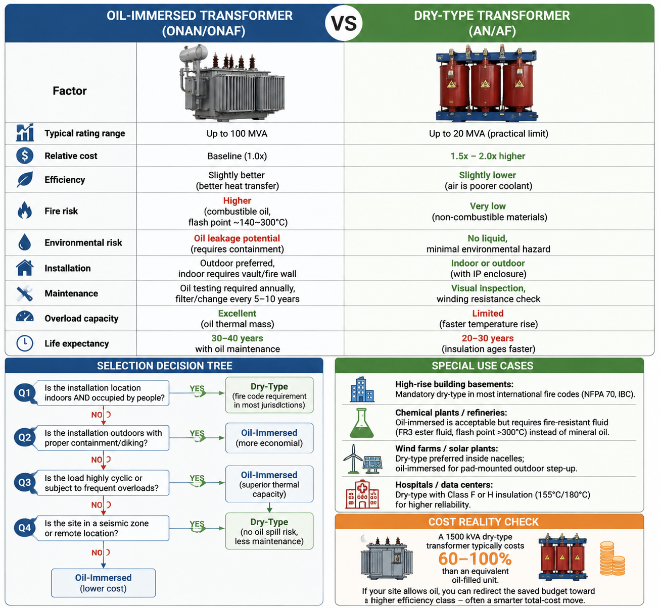
Comparative Selection Framework
Factor |
Oil-Immersed (ONAN/ONAF) |
Dry-Type (AN/AF) |
Typical rating range |
Up to 100 MVA |
Up to 20 MVA (practical limit) |
Relative cost |
Baseline (1.0x) |
1.5x – 2.0x higher |
Efficiency |
Slightly better (better heat transfer) |
Slightly lower (air is poorer coolant) |
Fire risk |
Higher (combustible oil, flash point ~140–300°C) |
Very low (non-combustible materials) |
Environmental risk |
Oil leakage potential (requires containment) |
No liquid, minimal environmental hazard |
Installation |
Outdoor preferred, indoor requires vault/fire wall |
Indoor or outdoor (with IP enclosure) |
Maintenance |
Oil testing required annually, filter/change every 5-10 years |
Visual inspection, winding resistance check |
Overload capacity |
Excellent (oil thermal mass) |
Limited (faster temperature rise) |
Life expectancy |
30–40 years with oil maintenance |
20–30 years (insulation ages faster) |
Selection Decision Tree
Q1: Is the installation location indoors AND occupied by people?
- YES: Dry-Type (fire code requirement in most jurisdictions)
- NO: Go to Q2
Q2: Is the installation outdoors with proper containment/diking?
- YES: Oil-Immersed (more economical)
- NO: Dry-Type (to prevent environmental liability)
Q3: Is the load highly cyclic or subject to frequent overloads?
- YES: Oil-Immersed (superior thermal capacity)
- NO: Either, based on cost preference
Q4: Is the site in a seismic zone or remote location?
- YES: Dry-Type (no oil spill risk after earthquake, less maintenance)
- NO: Oil-Immersed (lower cost)
Special Use Cases:
- High-rise building basements: Mandatory dry-type in most international fire codes (NFPA 70, IBC).
- Chemical plants / refineries: Oil-immersed is acceptable but requires fire-resistant fluid (FR3 ester fluid, flash point 300°C) instead of mineral oil.
- Wind farms / solar plants: Dry-type preferred inside nacelles; oil-immersed for pad-mounted outdoor step-up.
- Hospitals / data centers: Dry-type with Class F or H insulation (155°C/180°C) for higher reliability.
Cost Reality Check:
A 1500 kVA dry-type transformer typically costs 60–100% more than an equivalent oil-filled unit. If your site allows oil, you can redirect the saved budget toward a higher efficiency class – often a smarter total-cost move.
Step 4: Determine the Efficiency Class – Balancing First Cost and Energy Losses
The Most Financially Consequential Decision
A transformer's efficiency isn't just a technical spec – it's an operating cost annuity. The difference between a Tier 3 and Tier 1 unit can translate to tens of thousands of dollars in electricity bills over the transformer's life.
Understanding Loss Components
Loss Type |
What It Is |
When It Occurs |
How to Reduce |
No-load loss (iron loss) |
Hysteresis + eddy currents in core |
24/7, regardless of load |
Use amorphous metal or high-grade grain-oriented silicon steel |
Load loss (copper loss) |
I²R heating in windings |
Proportional to load² |
Increase conductor cross-section, use copper over aluminum |
Efficiency Standards Reference (IEC / IEEE / China GB)
Efficiency Tier |
GB 20052-2020 (China) |
IEC 60076-20 |
Typical Loss Level |
Tier 3 (Standard) |
Level 3 |
Standard |
Baseline losses |
Tier 2 (High) |
Level 2 |
High efficiency |
~20% lower losses |
Tier 1 (Premium) |
Level 1 (SCB18 for dry, S22 for oil) |
Premium / Super-Premium |
~30–40% lower losses |
Amorphous Metal |
Beyond Tier 1 |
Special category |
No-load loss reduced by 60–70% |
The Payback Calculation – Your Most Important Selection Tool
This is where engineering meets finance. Here's the formula every buyer should use:
Annual Energy Loss Cost = (No-load Loss × 8760 × Electricity Price) + (Load Loss × Load Factor² × 8760 × Electricity Price)
Worked Example – Comparing Tier 3 vs. Tier 1 for a 1000 kVA transformer:
Parameter |
Tier 3 Unit |
Tier 1 Unit |
Difference |
First cost |
$12,000 |
$18,500 |
+$6,500 |
No-load loss |
1.8 kW |
1.1 kW |
-0.7 kW |
Load loss (@100%) |
10.5 kW |
8.0 kW |
-2.5 kW |
Load factor |
65% |
65% |
Same |
Annual loss cost calculation (Electricity price: $0.12/kWh):
Tier 3: (1.8×8760×0.12) + (10.5×0.65²×8760×0.12) = $1,892 + $4,669 = $6,561/year
Tier 1: (1.1×8760×0.12) + (8.0×0.65²×8760×0.12) = $1,156 + $3,555 = $4,711/year
Annual savings: $1,850
Simple payback = $6,500 $1,850 = 3.5 years
Decision Rule: If payback is <5 years, choose higher efficiency. If >7 years, choose lower tier unless mandated by regulation.
The Load Factor Multiplier Table – Use this to adjust your decision:
Annual Operating Hours |
Load Factor |
Tier Upgrade Payback Threshold |
6,000 (continuous) |
60% |
Almost always worth it |
3,000 – 6,000 |
50% – 60% |
Evaluate case-by-case |
< 3,000 |
< 50% |
Likely not worth the premium |
< 1,500 (standby) |
< 30% |
Buy the cheapest compliant unit |
Amorphous Metal Consideration: These cores cut no-load loss by 60-70% but cost 30-50% more and have larger physical size. Ideal for low-load-factor, always-on applications like telecom towers, security systems, or residential distribution where load is light but service is continuous.
Step 5: Decide on Impedance Voltage and Tapping Range for Grid Stability
The Two Most Overlooked Yet Critical Parameters
While capacity and efficiency dominate conversations, impedance voltage (Zk%) and tapping range determine whether your transformer will actually deliver stable voltage under real-world grid conditions.
Impedance Voltage (Zk%) – The Invisible Hand
Zk% represents the voltage drop across the transformer at full load. It directly affects:
What Zk% Controls |
Higher Zk% (e.g., 8-10%) |
Lower Zk% (e.g., 4-6%) |
Short-circuit current |
Lower (reduces stress on downstream breakers) |
Higher (requires higher-rated switchgear) |
Voltage regulation |
Worse (voltage dips more under load) |
Better (voltage stays stable) |
Parallel operation |
Must match other transformers closely |
Must match other transformers closely |
Motor starting impact |
Less severe voltage sag on neighboring loads |
More severe sag |
Selection Guideline by Application:
Application |
Recommended Zk% |
Reasoning |
General industrial (mixed loads) |
6% |
Balanced compromise |
Heavy motor starting (50% of capacity) |
8% – 10% |
Limit inrush current impact |
Welding / highly fluctuating loads |
8% – 10% |
Prevent voltage flicker |
Commercial buildings (lighting + HVAC) |
4% – 5% |
Tight voltage regulation needed |
Networks with very high fault current capacity |
≥ 10% |
Protect downstream equipment |
Paralleled transformers |
Must match within ±10% of each other |
Avoid circulating currents |
Critical Warning: Changing Zk% affects physical dimensions and cost. Each 1% increase in Zk typically increases transformer cost by 3-5% due to additional winding turns and core volume.
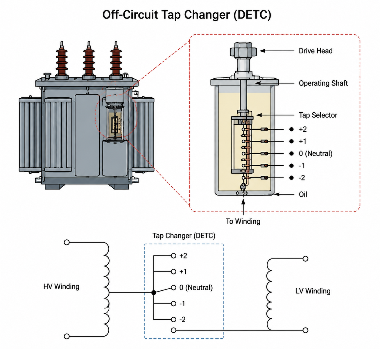
Tapping Range – Adjusting to Real-World Voltage
Utility supply voltage is never perfectly constant. Taps allow you to adjust the transformer's turns ratio to compensate.
Tap Configuration |
Common Range |
Best Use Case |
Off-circuit taps (DETC – De-Energized Tap Changer) |
±2×2.5% or ±5% |
Stable grid, set once during installation |
On-load taps (OLTC – On-Load Tap Changer) |
±4×2.5% or wider |
Grid with ±10% voltage swings, remote locations, critical facilities |
No taps |
Fixed ratio |
Small transformers (<500 kVA) with stable supply |
How to Choose:
- Measure the utility's actual voltage variation over a full week – if it stays within ±5%, DETC is sufficient.
- If variation exceeds ±5%, specify OLTC or request utility to improve supply quality.
- For dual-voltage applications (e.g., 10kV/20kV primary), specify the appropriate tap arrangement at order.
Tapping Selection Example:
Utility nominal: 11 kV
Actual measured: 10.2 kV (minimum) to 11.8 kV (maximum) = ±7.3% swing
Recommended: OLTC with ±4×2.5% = ±10% range, or specify DETC with ±5% and verify if within your equipment tolerance
The Voltage Drop Check – Before finalizing, calculate the voltage at the transformer secondary at full load:
Secondary Voltage = Rated Secondary × (1 – Zk% × Load Per-Unit)
If the result is below your equipment's minimum acceptable voltage (e.g., 380V -10% = 342V for 400V systems), you need either lower Zk% or a higher secondary tap setting.
Step 6 (Consolidated into Step 5): Accessories and Protection Systems
Note: The previous outline had 6 steps – this section incorporates the essential accessories discussion as it directly affects selection decisions.
Mandatory Accessories to Specify:
Accessory |
Function |
Selection Criteria |
Temperature sensors (PT100 / thermistor) |
Monitor winding and oil temperature |
Required for all units 630 kVA; specify number of sensors per phase |
Oil level gauge |
For oil-immersed units only |
Check level during installation and periodically |
Pressure relief device |
Safety release for overpressure |
Mandatory on oil-filled units 1 MVA |
Buchholz relay |
Gas detection for oil-insulated transformers |
Required for 1 MVA; indicates internal arcing |
Surge arresters |
Protect against lightning/switching surges |
Required for outdoor installations; select based on system BIL level |
Cooling fan set |
Increases capacity (ONAF vs. ONAN) |
Add 33% capacity for intermittent overload situations |
Enclosure / IP rating |
Weather and ingress protection |
IP20 (indoor), IP54 (outdoor/dusty), IP65 (washdown areas) |
Selection Tip: Do not automatically accept the manufacturer's standard accessory package. Review each item against your site conditions and regulatory requirements.
FAQ – Frequently Asked Questions in Transformer Selection
Q1: Can I run a transformer continuously at 100% of its rated load?
Technically yes, at rated ambient temperature (usually 40°C average, 20°C daily average per IEC). However, continuous 100% loading accelerates insulation aging. The industry practice is to design for 70-80% average loading to allow for growth and emergency overload capacity.
Q2: How much overload can a transformer handle?
Duration |
Oil-Immersed |
Dry-Type |
2 hours |
30% overload acceptable |
20% acceptable |
4 hours |
20% acceptable |
10% acceptable |
Continuous |
Not recommended |
Not recommended |
Overload capability depends on prior loading history and ambient temperature – consult IEEE C57.91 for precise calculations.
Q3: Is aluminum winding acceptable, or should I always choose copper?
Aluminum is acceptable and common, particularly in standard-efficiency units. However:
- Copper offers: Lower losses, smaller physical size, better connections (no galvanic corrosion issues), higher short-circuit strength
- Aluminum offers: Lower first cost (typically 15-25% cheaper), but requires larger cross-section (about 1.6x copper), and termination requires special care
Decision: For critical applications, <1% downtime tolerance, or high cyclic loads → choose copper. For general commercial, non-critical, or tight-budget projects → aluminum may be the right choice.
Q4: What is the difference between AN, AF, ONAN, and ONAF?
Code |
Meaning |
Cooling Method |
AN |
Air Natural |
Dry-type, still air |
AF |
Air Forced |
Dry-type with fans |
ONAN |
Oil Natural Air Natural |
Oil-immersed, natural convection |
ONAF |
Oil Natural Air Forced |
Oil-immersed with forced-air fans |
Selection: ONAF increases capacity by 33% for the same physical unit – specify if you anticipate occasional overloads.
Q5: How do I handle harmonic loads (VFDs, UPS, rectifiers)?
Harmonics cause additional losses and heating. Common practice:
- If harmonic content (THD) 15%, specify a K-rated transformer or install harmonic filters.
- K-factor ratings: K=1 (linear loads), K=4 (moderate harmonics), K=9 (high harmonics), K=13 (severe harmonics, typical for data centers/VFD-heavy plants).
- Alternatively, use a zig-zag transformer to filter harmonics.
Q6: What clearances and fire protection are required for indoor installations?
Building Type |
Oil-Immersed |
Dry-Type |
Human-occupied |
Requires vault/fire wall or prohibited |
No special clearance beyond NEC |
Non-occupied |
Requires fire wall and oil containment |
No special requirement |
Always check local fire code – many jurisdictions prohibit oil indoors entirely.
Q7: How important is the tank paint color for outdoor units?
More important than you think – dark colors absorb solar heat, raising internal temperature. Specify light-colored paint (RAL 7035 or similar) for outdoor units in tropical/sunny climates. This can reduce the thermal hotspot temperature by 5-10°C.
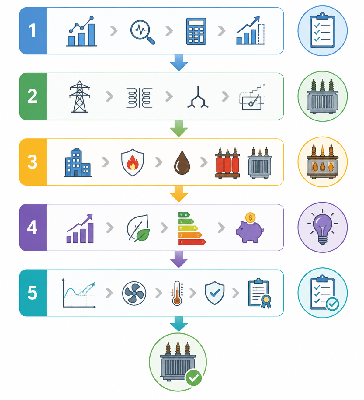
SUMMARY – The Five-Step Selection Framework
Selecting the right distribution transformer comes down to answering five core questions in sequence. Skip any one, and you risk overpaying, underperforming, or both.
Step 1: Load Analysis – Size for Reality, Not Nameplates
Base your capacity decision on actual measured peak demand and average load factor, not the sum of all connected equipment tags. Oversizing wastes capital and inflates no-load losses; undersizing shortens transformer life. Always factor in a 10–15% growth margin and verify that your selected kVA accommodates both current peaks and near-term expansion.
Step 2: Voltage Match – Get the Input and Output Right
Confirm the utility's actual primary voltage through on-site measurement, not just nominal ratings. Select the secondary voltage to match your end-use equipment, and choose the connection type (Delta or Wye) based on whether you need a neutral for single-phase loads. Specify an appropriate tap range to handle normal utility voltage swings without compromising output stability.
Step 3: Type Selection – Let the Installation Site Decide
The oil-immersed vs. dry-type choice is driven almost entirely by environment and fire safety. Dry-type is mandatory for most indoor, occupied spaces and offers lower fire risk and minimal environmental concerns—but costs significantly more. Oil-immersed is more economical, handles overloads better, and lasts longer, but requires outdoor placement or proper containment for fire and spill protection.
Step 4: Efficiency Class – Run the Payback Math
Never choose an efficiency tier based on first cost alone. Calculate the annual cost of no-load and load losses using your actual load factor and operating hours. If the price premium for a higher-tier unit pays back in under five years, upgrade. If payback exceeds seven years, stick with the baseline compliant tier. For continuous 24/7 operation, higher efficiency almost always makes financial sense.
Step 5: Impedance and Final Specifications – Confirm Grid Compatibility
Select impedance voltage (Zk%) based on your application—lower values (4–6%) for tight voltage regulation in commercial buildings, higher values (8–10%) for heavy motor starting or high fault-current networks. Verify that the chosen Zk% works with your upstream switchgear ratings. Finally, confirm all accessories (temperature sensors, cooling method, enclosure IP rating) match your site conditions and regulatory requirements.
5-Step Distribution Transformer Selection Process Guide
The Golden Rule
There is no single "best" transformer—only the one that best fits your specific load, site, grid, and economic profile. Work through these five steps in order, document every decision, and you will specify a transformer that delivers reliable service at the lowest total cost over its lifetime.
Choosing Jiangsu Unita Electric Equipment Co.,Ltd.(JSZONMA)means partnering with a national high-tech enterprise with over a decade of expertise and a 46,600 m² self-owned manufacturing facility. As a qualified supplier for both State Grid and China Southern Power Grid, JSZONMA offers one-stop services ranging from 10kV energy-efficient transformer customization to complete substation EPC solutions. With factory-direct pricing and full-chain quality control, JSZONMA ensures reliable delivery and long-term performance—making us your trusted partner for every critical project.
Thank you for reading. If you have any technical questions or specific project requirements, our engineering team is always ready to assist you.