EN
EN


News
Distribution Transformer Installation Procedure: Complete Guide, Steps, Checklist and Common Mistakes
Installing a distribution transformer correctly is one of the most critical tasks on any electrical project. Get it right, and the transformer will deliver decades of reliable service. Get it wrong, and you're looking at costly downtime, equipment damage, or even serious safety hazards.
This guide walks through the complete installation process from site prep to energization, highlights the most common mistakes contractors make, and shows exactly how to avoid them.
1. Distribution Transformer Installation: The Complete Step-by-Step Process
A successful installation follows a logical sequence. Skipping steps or taking shortcuts is where problems start.
1.1 Site Selection and Preparation
The transformer location sets the foundation for everything that follows. The site must be well-ventilated and free from excessive dust or corrosive fumes. If installed indoors, maintain a clear space of approximately 1.25 meters on all sides to allow proper heat dissipation and maintenance access.
The foundation itself must be firm, level, and dry. For pole-mounted transformers, the base channel must meet height requirements—typically a minimum of 4.57 meters for the top of HV bushings. For plinth-mounted units, this minimum is 2.75 meters.
Key site considerations:
- Good drainage to prevent water pooling around the unit
- Adequate clearance from walls and other equipment (0.6m to 1.2m minimum, depending on rating)
- Grounding infrastructure must be installed and tested before the transformer arrives
1.2 Assembly of Dismantled Components
Transformers are often shipped with components disassembled to prevent transit damage. The assembly process must follow the manufacturer's General Arrangement drawing.
Critical assembly steps:
Bushings:
- Clean thoroughly
- Check for cracks
- Test IR with 500V Megger (greater than 100 MΩ required)
Conservator:
- Mount per GA drawing
- Install Magnetic Oil Level Gauge
- Ensure float moves freely
Buchholz Relay:
- Release tied floats
- Verify arrow direction points toward conservator
- Set test lever to working position
Radiators:
- Assemble one at a time
- Test oil BDV before filling
- Bleed air from top plugs
Breathers:
- Check silica gel is blue
- Remove shipping seals
- Fill oil cup
Torque values matter. Over-tightening or under-tightening connections is a common failure point. Here are the recommended torque values in Nm for various fastener applications:
For M10 bolts:
- Bushing Mounting: 15 Nm
- Copper Connections: 20 Nm
- Radiator/Gunmetal Valves: N/A
For M12 bolts:
- Bushing Mounting: 25 Nm
- Copper Connections: 35 Nm
- Radiator/Gunmetal Valves: 25 Nm
For M16 bolts:
- Bushing Mounting: 40 Nm
- Copper Connections: 80 Nm
- Radiator/Gunmetal Valves: 30 Nm
1.3 Oil Filling
Oil should never be filled directly from drums or transport containers—precipitated water or sediments may be pumped in along with the oil. Instead, fill into an oil storage tank first and test parameters before transferring to the transformer.
Two filling methods:
Method 1: Oil Filling Without Vacuum
Step 1: Install the air cell (flexi separator) inside the conservator with hooks properly engaged.
Step 2: Inflate the air cell to the pressure shown on the instruction plate.
Step 3: Keep air release valves open, start oil filling from the bottom filter valve.
Step 4: Close air release valves one by one as oil starts overflowing.
Step 5: Continue filling until the Magnetic Oil Level Gauge shows the level for ambient temperature.
Step 6: Install the silica gel breather.
CRITICAL: After oil filling completes, DO NOT open any air release valves—air will enter and the oil level will drop.
Method 2: Vacuum Filling
Step 1: Create vacuum in both the separator and conservator.
Step 2: Open oil filling valve—oil rises automatically due to vacuum.
Step 3: Stop at required volume.
Step 4: Admit dry air or nitrogen to inflate the separator.
Step 5: Check vent holes to confirm no air remains.
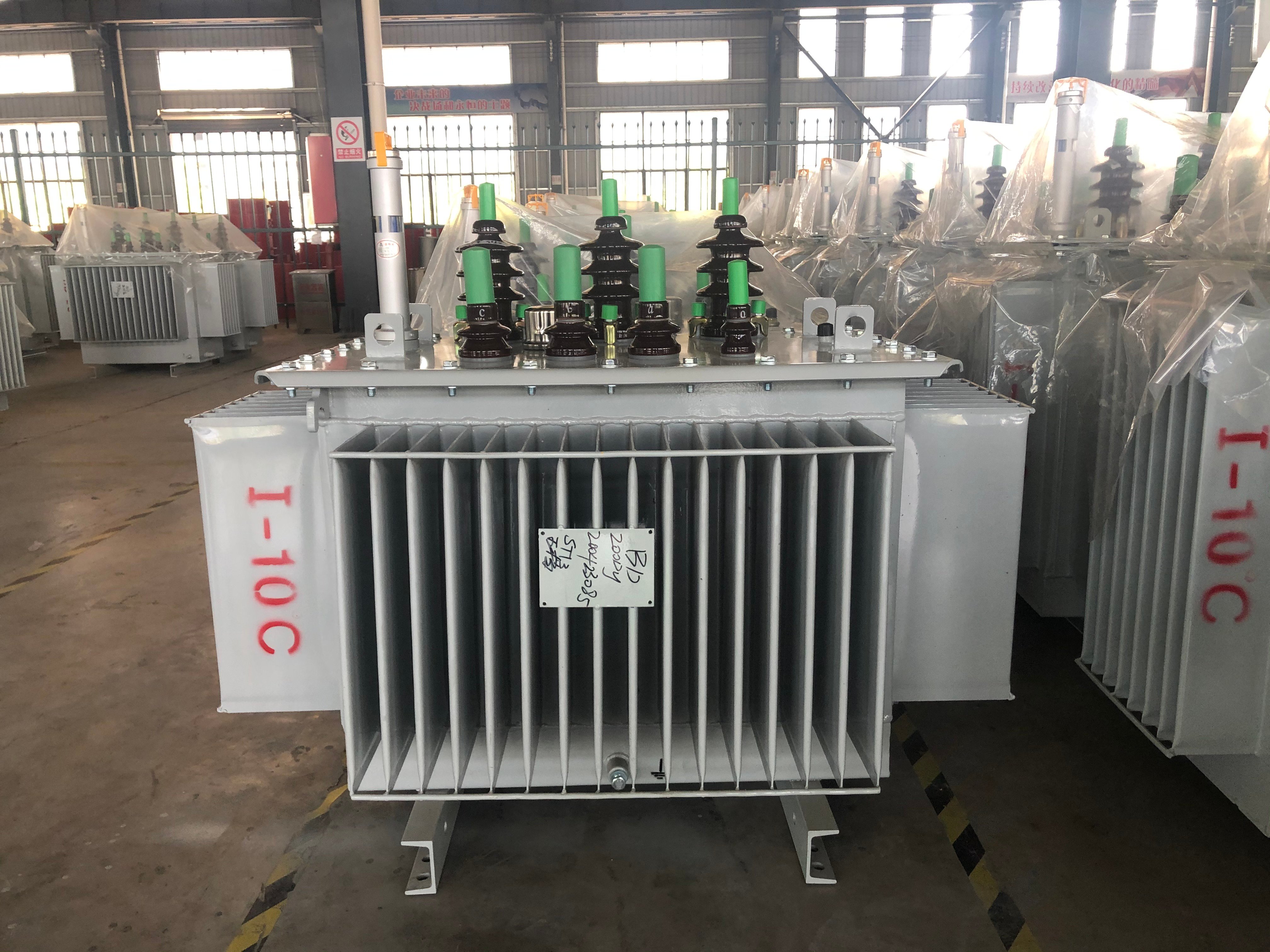
Looking for reliable distribution transformers for industrial or utility projects? Our oil immersed transformers are designed according to IEC standards with factory testing before delivery.
1.4 Earthing (Grounding) System
Proper earthing is non-negotiable for safety and regulatory compliance. As per IE rules, the neutral bushing and transformer body must be earthed by at least two separate and distinct connections with different earth electrodes.
Standard practice:
- Excavate three earth pits arranged in an equilateral triangle (typically 8 feet deep)
- One pit for lightning arrestors
- One pit for transformer neutral earthing
- One pit for body earthing
- Interconnect all three electrodes to form an earth bus approximately 1 foot below ground
Acceptable resistance values:
- Interconnected electrodes: less than or equal to 2.5 Ω
- General earthing system: less than 30 Ω per Western Power standards
2. Common Installation Problems (At a Glance)
Based on field experience and industry data, here are the most frequently encountered installation issues:
Category: Foundation
Common Problem: Pole depth insufficient; base not level
Category: Positioning
Common Problem: Clearance violations; incorrect bushing orientation
Category: Connections
Common Problem: Loose terminals; wrong torque; phase reversal
Category: Oil Handling
Common Problem: Contaminated oil introduced; incorrect filling procedure
Category: Earthing
Common Problem: Insufficient grounding; high resistance readings
Category: Component Assembly
Common Problem: Buchholz relay installed backwards; breather seals not removed
3. Deep Dive: Why These Problems Occur and How to Avoid Them
Problem 1: Insufficient Pole Depth for Pole-Mounted Transformers
Why it happens:
Contractors rushing foundation work or working from memory rather than specifications.
The fix:
For 15m and shorter concrete poles, the formula is one-tenth of pole height plus 700mm. Example: a 12m pole requires 1.2m plus 0.7m equals 1.9m depth. Acceptable tolerance is +100mm and -50mm.
Pro tip: Verify pole depth before backfilling. Once the transformer is on top, corrections are expensive.
Problem 2: Improper Bolt Torque
Why it happens:
Good and tight is subjective. Different applications (bushing mounts vs. copper connections) require different torque values.
The fix:
Use a calibrated torque wrench and follow the torque table above. Loose connections cause arcing and overheating. Over-tightened connections can crack bushings or strip threads.
Problem 3: Buchholz Relay Installed Backwards
Why it happens:
The relay looks symmetrical, and the arrow marking is easy to miss.
The fix:
The arrow on the Buchholz relay must point toward the conservator. Installing it backward means gas accumulation won't trigger the alarm or trip function—a serious safety risk.
Problem 4: Contaminated Oil Introduction
Why it happens:
Oil pumped directly from drums that may contain moisture or sediment from storage.
The fix:
Always transfer oil from drums to a storage tank first, then test BDV (Breakdown Voltage) before filling the transformer. The BDV must exceed the minimum specified in standards like I.S. 1866 for new transformers.
Problem 5: Inadequate Grounding
Why it happens:
Ground rods not driven deep enough; connections not properly welded; resistance not measured.
The fix:
Measure earth resistance before energizing. If resistance exceeds acceptable limits (typically 2.5 to 10 Ω depending on standard), add additional ground rods or improve the soil condition.
Problem 6: Insufficient Clearance
Why it happens:
Trying to save space or not consulting the manufacturer's requirements.
The fix:
For transformers up to 1000kVA, minimum clearances are 0.9m front, 0.6m sides and rear. These dimensions ensure both ventilation and maintenance access. For larger units, increase accordingly.
Problem 7: Breather Seals Not Removed
Why it happens:
Overlooked during assembly; the sealing cap blends in.
The fix:
The breather pipe comes with a rubber cap for shipping. Remove it before operation. The silica gel breather also requires oil in the oil cup and removal of the sealing plug. If forgotten, the transformer cannot breathe—pressure builds and oil leaks result.
4. Post-Installation Inspection Checklist
Before energizing, complete this verification list. A standardized commissioning form is recommended.
Visual and Mechanical Checks
- Transformer matches system voltage and rating plate
- Tap changer set to the position specified by network planning
- Tank and bushings in good condition—no cracks, no oil leaks
- Oil level (if visible) is within acceptable range
- All temporary shipping restraints removed
- All bolts torqued to specification
- Breather seals removed; silica gel color is blue (not pink)
- Cable labels installed (temporary acceptable, permanent to follow)
- Work area clear of debris and hazards
Insulation Resistance Tests
Test Connection: HV to Tank
Test Voltage: 2.5 kV
Acceptable Minimum: greater than 1 GΩ
Test Connection: HV to LV
Test Voltage: 1 kV
Acceptable Minimum: greater than 100 MΩ
Test Connection: LV to Tank
Test Voltage: 1 kV
Acceptable Minimum: greater than 100 MΩ
Alternative guideline: for 6.6 to 11kV windings, minimum safe IR is 200 to 400 MΩ with a 1000V Megger.
Earthing Verification
- Earth resistance test performed and documented
- Resistance meets applicable standard (less than or equal to 2.5Ω per IE rules)
- All earth connections tight and secure
- N-E link connected
Pre-Energization Steps
Step 1: Ensure LV side is disconnected from the network (all LV fuse ways open)
Step 2: Verify HV fuse rating is correct for the transformer capacity
Step 3: Energize transformer on no-load first
Step 4: Listen for abnormal noise during energization
Step 5: Measure secondary voltages:
- Phase-to-neutral: 226 to 254 V (within statutory limits)
- Phase-to-phase: 390 to 440 V
Step 6: Check phase rotation—must be 123/ABC/RWB sequence
Step 7: If phase rotation is reversed, interchange any two phases at the LV switch
Load Test
- Apply load and verify all measurements remain within limits
- Check that any connected motors rotate in the correct direction
- Record final no-load voltages for documentation
Handover
- Complete commissioning report with all test results
- Install permanent cable and equipment labels
- Submit handover certificate to the operating authori

5. Frequently Asked Questions
Q1: What's the most common cause of transformer installation failure?
A: Loose or incorrectly torqued connections top the list. Arcing from loose terminals generates heat, degrades insulation, and can lead to catastrophic failure. Always use a calibrated torque wrench.
Q2: How long does a typical distribution transformer installation take?
A: A straightforward pole-mounted transformer installation with all materials on site typically takes 4 to 8 hours. Larger pad-mounted or substation units may take 2 to 3 days, especially if oil filling and testing are involved.
Q3: Can I reuse oil from the old transformer?
A: Not recommended unless it has been tested and filtered. New oil or factory-tested oil is the safest option. If reusing, perform a BDV test and moisture analysis before transfer.
Q4: What should I do if the insulation resistance test fails?
A: The transformer likely has moisture ingress. It must be dried out using an oil filtration or vacuum drying process before energizing. Energizing with low IR values risks internal arcing and winding damage.
Q5: Why does the Buchholz relay have an arrow on it?
A: The arrow indicates the correct orientation—it must point toward the conservator. Gas bubbles generated in the tank travel up toward the conservator; the relay detects them only if installed in the right direction.
Q6: What's the difference between vacuum and non-vacuum oil filling?
A: Vacuum filling removes dissolved moisture and gases from the oil and eliminates air pockets in the winding insulation. It's the preferred method for larger transformers. Non-vacuum filling is simpler and acceptable for smaller units, but carries a higher risk of trapped air.
Q7: How often should silica gel breather media be replaced?
A: When the silica gel changes from blue to pink, it has absorbed moisture and needs to be dried or replaced. Check it during every routine maintenance visit.
Q8: Is a separate earth pit required for lightning arrestors?
A: Yes. Standard practice uses three separate earth pits—one for lightning arrestors, one for transformer neutral, and one for body earthing—interconnected to achieve low overall resistance.
6. Summary
Distribution transformer installation success comes down to attention to detail at every stage. The contractors who avoid costly callbacks and equipment failures follow these principles:
- Prepare the site properly. Level foundation, adequate clearance, and drainage are non-negotiable.
- Inspect everything before assembly. Bushings, oil, and components must arrive damage-free.
- Torque to specification. Never guess. Use the torque table and a calibrated wrench.
- Oil handling is critical. Never pump directly from drums. Test BDV before filling.
- Buchholz relay orientation matters. The arrow must point toward the conservator.
- Grounding is safety. Test resistance and verify it meets standards before energizing.
- Follow the commissioning checklist. Insulation tests, voltage checks, and phase rotation verification protect both equipment and personnel.
- Document everything. The commissioning report is your proof of quality work and protects you from future liability.
A well-installed transformer is forgotten. A poorly installed transformer is remembered—usually at 2 AM on a weekend.
Invest the time upfront to do it right. Your reputation—and your customer's power supply—depends on it.
For more information, please contact our transformer engineers for customized distribution transformer solutions.