 EN

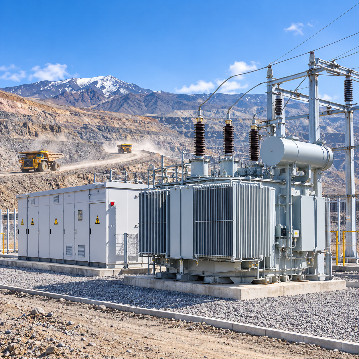
Remote mining projects in Central Asia, South America and other off-grid regions face a power distribution problem that grid-connected plants do not: the mine must supply its own voltage and frequency support while absorbing some of the heaviest impact loads in industry. Large mill motors start direct-on-line, shovels and drills cycle unpredictably, and crushers produce fluctuating, harmonic-rich demand - often hundreds of kilometres from a competent maintenance base. For project owners, the equipment selected at the procurement stage largely determines whether the microgrid achieves high availability or becomes a production bottleneck.
1. Reliability and backup power in islanded mining microgrids
In an islanded mining microgrid, a large motor start is a system-wide event. The starting current flows from the on-site generators, transformers and any battery energy storage online, producing a voltage dip that affects every motor control centre on the same bus. Contactor drop-out, VFD tripping and cascading process stops can follow. Diesel generators remain essential for backup and gap-filling, but they cannot economically provide fast frequency and voltage support at low load factors. Battery energy storage is increasingly used to supply that fast response, while generators and transformers must be specified for the worst credible starting scenario - not only steady-state load.
This changes the specification logic for distribution equipment. Transformers and switchgear must be rated for transient voltage and current excursions, and protection settings must be coordinated with the microgrid's fault contribution from generators, storage and motors.
2. Motor starting, impact loads and transformer selection
The most consequential choice for a mining distribution transformer is short-circuit impedance. Lower impedance reduces voltage dip during a large motor start, but it raises prospective short-circuit current at the secondary terminals - driving up the withstand requirements for medium-voltage switchgear, cables and busbars downstream. The transformer may be marginally cheaper; the switchgear and cables are not.
For oil-immersed distribution transformers feeding motor control centres, a practical impedance range is often 5-6 percent, balancing motor-starting voltage support against fault current that downstream switchgear can handle cost-effectively. The transformer must be sized for running load plus the starting kVA of motors that actually start together, then checked against the acceptable voltage-dip limit at the motor terminals and adjacent MCC buses. Where VFD penetration is high, harmonic loading and additional winding heating must also be considered.
Oil-immersed transformers retain an advantage here: the liquid cooling medium provides thermal mass and overload tolerance that dry-type units struggle to match in high-ambient, high-dust environments - provided the tank sealing and oil preservation system suit the site.
3. Environmental derating: altitude, cold, dust and transport
IEC altitude correction above 1,000 m is widely known but often misapplied. The standard assumes clean air and ambient temperatures within the -5 C to +40 C band. When high altitude combines with conductive dust - common in Central Asian and Andean mining environments - dust deposits reduce surface flashover voltage beyond what pressure correction predicts. The correct response is a combined correction: altitude-based insulation compensation, increased creepage distance, higher IP ratings and anti-condensation measures.
Cold climate adds another layer. In northern Kazakhstan and other Central Asian mining regions, low-temperature oil formulations and cold-rated accessories determine whether a transformer can be energised and loaded at -40 C without derating or auxiliary heating. At the same time, the same unit must shed heat at +40 C summer ambient, so cooling mode selection - ONAN versus ONAF - must follow the actual site ambient envelope, not factory reference conditions.
Dust also dictates switchgear enclosure strategy. Air-insulated switchgear relies on atmospheric air for insulation and cooling; in a dusty open-pit or concentrator environment, that air is a liability. Gas-insulated or shielded solid-insulated switchgear removes live parts from contact with the site atmosphere and can be applied at high altitude without voltage derating, making it the more defensible choice for the main MV switchboard and critical MCCs.
Transport constraints are the third environmental variable. A transformer or E-house that exceeds the weight or dimensional envelope of the available road or rail route is not a bargain, regardless of factory price. Skid-mounted and containerised substations reduce site civil works and commissioning time - typically from 30-60 days for stick-built permanent substations to 5-10 days for pre-integrated mobile units - but only if engineered to the actual transport corridor from factory to mine gate.
4. Equipment configuration for remote mining distribution
A remote mining microgrid distribution system typically resolves into three functional layers.
Oil-immersed distribution transformers
These remain the workhorse for mine distribution at medium voltage, provided they are specified for the site's ambient temperature range, altitude and dust exposure. For Central Asian projects, this means EAC/GOST-compliant documentation and cold-climate oil and accessory configurations. For Chile and Peru, the mining sector's historical preference for ANSI/NEMA switchgear means transformer secondary voltage and impedance must match ANSI-rated downstream equipment, even where the national grid standard is IEC.
Compact substations and E-houses
These package the transformer, MV switchgear, LV distribution, protection and control into a factory-integrated enclosure. Their value is not convenience but the shift of integration and routine testing from a construction camp with limited QA capability to a controlled factory environment. The enclosure must be specified for the site's dust ingress rating, anti-condensation performance and internal temperature rise under actual solar and ambient load.
MV and LV switchgear
Switchgear connects incoming transformers and local generation to distribution feeders, while MCCs house contactors, soft starters and VFDs. Switchgear is less than 30 percent of mining power system CAPEX, but a single failure in the main board can take down the entire plant. Specification should prioritise internal arc-tested enclosures, comprehensive interlocks, and protection coordinated with transformer impedance and the motor-starting profile.
5. Pre-purchase technical confirmation checklist
Site and system basis
- Confirm altitude, maximum and minimum ambient temperatures, and dust or contaminant classification; require site-specific combined derating.
- Confirm 50 Hz versus 60 Hz supply and local grid code or utility interconnection requirements.
- For Central Asia, confirm EAC/GOST certification and low-temperature oil and accessory specifications; for Chile and Peru, confirm whether ANSI/NEMA switchgear standards apply.
Transformer specification
- State the largest motors that can start simultaneously, their starting kVA and current profile, and the acceptable voltage dip at motor terminals and adjacent MCC buses.
- Specify transformer impedance as an optimised value, not a default; confirm it does not impose an unmanageable short-circuit level on downstream MV switchgear.
- Specify cooling mode (ONAN or ONAF) against actual site ambient, and confirm rated power at maximum ambient without forced cooling.
- For oil-immersed units, confirm oil type for minimum ambient, tank sealing method and oil preservation system.
Switchgear and protection
- Choose the insulation strategy for dust exposure: AIS only where enclosure and ventilation exclude conductive dust; GIS or SSIS for high-dust or high-altitude main boards.
- Confirm internal arc classification and arc-resistant construction for the main MV switchboard.
- Require protection coordination studies covering transformer impedance, motor-starting inrush and fault contribution from generators and storage.
Packaging, transport and verification
- Confirm the transport envelope - weight, dimensions, lifting points - against the actual route to site; require transport engineering drawings before PO release for skid-mounted or containerised substations.
- Specify FAT scope: transformer routine tests per IEC 60076-1 and switchgear routine tests per IEC 62271-200; request IEC type test reports for the design family, not only unit routine certificates.
- Confirm site commissioning scope and whether factory integration testing can reduce on-site energisation time.
6. Matching equipment to the operating envelope
No single catalogue product fits both Central Asian cold and dusty sites and South American high-altitude, seismic-zone mines. Oil-immersed distribution transformers deliver the thermal robustness and overload tolerance mining motor loads demand, but their oil system, sealing and accessories must be configured for cold-start and dust-ingress realities. Compact substations reduce site integration risk only when enclosure thermal and ingress design derives from the actual ambient and contaminant profile. MV switchgear protects availability, and its insulation strategy must be chosen against dust and altitude conditions that degrade air-insulated designs.
Jiangsu Unita's product scope - oil-immersed distribution transformers, compact box-type substations, and MV/LV switchgear - maps directly onto these three equipment layers for Central Asian, South American and other remote mining markets. The procurement discipline that matters is the same regardless of supplier: require transformer impedance to be justified against the motor-starting study, require environmental corrections to be calculated rather than assumed, and require factory test evidence to cover the design family and site-specific configuration.
A remote mining microgrid has no slack for equipment selected on catalogue headlines rather than on the electrical and environmental envelope it will actually face.
7. Application scenarios and equipment mapping
The same three equipment layers apply beyond mining. The table below maps typical duty profiles to the specification points that decide whether an installation holds up in service.
Application scenario |
Distribution-side requirement |
Recommended equipment configuration |
Solar PV plants |
Inverter-fed MV collection, harmonic loading and wide day-night ambient swing, often at high-altitude desert sites. |
Oil-immersed collection transformers with ONAN/ONAF rated at maximum ambient; GIS or SSIS MV collection switchgear; anti-condensation heating and extended creepage. |
Wind farms |
Frequent switching and load swings, converter harmonic currents, tight transport corridors up to ridge-line substations. |
Compact box-type substations assembled and routine-tested as one factory unit; internal arc-tested MV switchgear with full interlocks; LV collection panels. |
Energy storage systems |
Fast frequency and voltage support, high cycling duty, protection settings that must follow inverter fault contribution. |
Transformer impedance justified against the storage fault contribution; coordination study covering BESS and motor inrush; skid-mounted containerised integration. |
Telecom base stations |
Remote or weak-grid sites, generator-backed load patterns, strict limits on floor space and maintenance visits. |
Small oil-immersed transformers with low-temperature oil and cold-rated accessories; shielded solid-insulated switchgear; pre-integrated E-house to cut site works. |
Mining sites |
Direct-on-line mill motor starts, impact loads from shovels, drills and crushers, conductive dust, -40 C cold or Andean altitude. |
Oil-immersed MCC feed transformers at an optimised 5-6 percent impedance; GIS or SSIS main MV switchboard; containerised substation engineered to the transport corridor. |
Table 1: Typical application scenarios, distribution-side requirements and recommended equipment configurations.
8. Frequently asked questions
Q1. Why is transformer short-circuit impedance the most consequential choice in a mining microgrid?
Because it sets a trade-off that ripples through the whole distribution system. Lower impedance limits the voltage dip during a large motor start, but it raises the prospective short-circuit current at the secondary terminals, so the medium-voltage switchgear, cables and busbars downstream must withstand more. The transformer may be marginally cheaper; the switchgear and cables are not.
Q2. What impedance is practical for oil-immersed transformers feeding motor control centres?
A band of 5-6 percent is generally workable in islanded mining systems, balancing motor-starting voltage support against a fault level that downstream switchgear can handle cost-effectively. The exact value should be justified against the motor-starting study rather than taken as a catalogue default, and re-checked where VFD penetration is high.
Q3. Is IEC altitude correction above 1,000 m sufficient for a dusty mine site?
No. The standard assumes clean air and an ambient band of -5 C to +40 C. Where altitude meets conductive dust, deposits reduce surface flashover voltage beyond what pressure correction predicts. The correct specification is a combined correction: altitude-based insulation compensation, increased creepage distance, higher IP ratings and anti-condensation measures.
Q4. Can diesel generators alone provide fast frequency and voltage support?
Generators remain essential for backup and gap-filling, but they cannot economically provide fast frequency and voltage support at low load factors. Battery energy storage increasingly supplies that fast response, while generators and transformers must be specified for the worst credible starting scenario rather than steady-state load alone.
Q5. How do compact substations reduce site risk, and what must be confirmed before PO release?
Factory integration moves assembly and routine testing from a construction camp with limited QA capability into a controlled factory, typically cutting commissioning from 30-60 days for stick-built substations to 5-10 days for pre-integrated units. Before PO release, confirm the enclosure ingress and internal thermal design against actual solar and ambient load, and confirm the transport envelope - weight, dimensions and lifting points - against the real route from factory to mine gate.
release
Table of Contents
- 1. Reliability and backup power in islanded mining microgrids
- 2. Motor starting, impact loads and transformer selection
- 3. Environmental derating: altitude, cold, dust and transport
- 4. Equipment configuration for remote mining distribution
- 5. Pre-purchase technical confirmation checklist
- 6. Matching equipment to the operating envelope
- 7. Application scenarios and equipment mapping
- 8. Frequently asked questions