EN

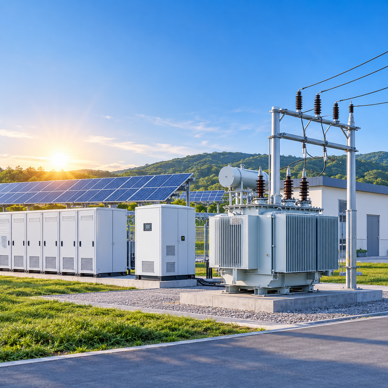
A microgrid is often described by its sources—PV arrays and battery racks—but the equipment that determines whether those sources actually behave well together sits in the middle: the transformer. In grid-tied mode, it is a power channel. In islanded mode, it becomes part of the voltage and frequency reference for the entire system. Getting the PV–PCS–transformer–load relationship right is therefore not a procurement detail; it is the architectural decision that decides whether a microgrid is stable, efficient, and long-lived.
The Electrical Chain: PV, PCS, Transformer, Load
A typical AC-coupled microgrid follows a clear sequence. PV strings feed DC into a power conversion system (PCS), which includes the inverter and, in medium-voltage designs, a step-up transformer. The PCS output is stepped up to medium voltage, collected, and then stepped down at the load side through distribution transformers. Battery storage connects through a bidirectional PCS to the same AC bus, allowing charge and discharge power to flow in either direction.
The transformer’s role differs by location. Step-up transformers on the generation side primarily serve energy-producing applications, taking inverter-level voltages (480–600 V) up to 10 kV, 34.5 kV, or higher for collection and transmission. Distribution transformers on the load side perform the reverse function, stepping medium voltage down to utilization levels. In a microgrid, both functions must coexist, and often the same transformer must support power flow in *both* directions depending on whether PV is exporting or the battery is charging.
Sizing the Transformer Against Inverter Output
Transformer capacity should not be treated as a simple 1:1 copy of inverter nameplate. Industry practice applies an oversizing factor of roughly 1.10 to 1.25 on the inverter’s AC rated output, adjusted for ambient temperature and altitude. The logic is straightforward: inverters can briefly overload, harmonic currents add heating burden, and the transformer must carry reactive power in islanded mode without saturating.
At the same time, the rated kVA of the transformer must be equal to or greater than the total nominal output of all inverters connected to it—a baseline requirement for coordinated protection and voltage regulation. For a 1 MW PV block, a 1250 kVA step-up transformer is a common fit; undersizing to save cost often produces a thermal bottleneck precisely when PV and battery discharge coincide.
Harmonics, Reverse Power Flow, and Thermal Stress
PV inverters and battery PCS units are non-linear sources. When many of them operate on the same transformer, harmonic currents superimpose and produce additional frequency-dependent losses in windings and cores. The problem is compounded by reverse power flow: as PV penetration rises, the transformer may spend hours exporting power back toward the grid or the point of common coupling, a condition for which conventional distribution transformers were not optimized.
Experimental and modeling work shows the thermal consequence. Under full-load reverse power flow combined with harmonic distortion, transformer lifetime expectancy can decrease by roughly 8.3%, and hotspots migrate in ways that accelerate insulation aging. In microgrids that switch frequently between import and export, cyclic duty matters more than average loading: thermal aging accumulates on peak temperature and cycle count, not on a smooth daily average.
Transformers specified for microgrid service need K-factor or harmonic-tolerant designs, adequate cooling, and insulation systems rated for repeated thermal cycling—not simply a standard distribution unit with a higher kVA label.
Grid-Tied vs. Islanded: Two Different Machines in One Frame
In grid-tied operation, the utility establishes voltage and frequency; the transformer largely passes power and provides galvanic isolation. The moment the point of common coupling opens, the dynamic changes. The transformer may need to work with BESS and PV inverters to anchor voltage and frequency, absorb magnetizing inrush, and ride through motor-starting currents that the main grid previously supplied.
Grounding is the most frequently overlooked difference. When the microgrid islands, the utility’s neutral grounding reference disappears. Without a grounding transformer, a single-phase-to-ground fault has no low-impedance return path; protection may not see the fault, and overvoltage can stress insulation. Impedance selection is equally consequential: a low-impedance transformer tightens voltage regulation but raises fault current, forcing every downstream breaker and switchgear rating to be revisited. A microgrid transformer therefore has to be specified against two operating realities—normal grid-tied loading and islanded fault/voltage support—rather than one.
Planning Interfaces and Responsibility Boundaries
Technical integration fails commercially when responsibility boundaries are ambiguous. The point of common coupling (PCC) is the natural physical and contractual separation: the distribution system operator manages the grid up to the PCC, and the microgrid operator manages everything behind it. In practice, however, ownership of the interconnection line, step-up station, and distribution assets is often unclear, and investment responsibility for grid reinforcement triggered by the microgrid is frequently disputed.
A workable interface plan assigns four things explicitly: equipment ownership (who owns the transformer, switchgear, and protection relays), setting authority (who configures protection and control at the PCC), testing responsibility (who commissions islanding detection and grounding performance), and data and control boundaries (what the microgrid controller can command versus what the utility retains). Equipment that supports clear physical demarcation—compartmentalized switchgear, dedicated grounding transformer bays, and transformer packages with defined protection interfaces—reduces the friction that otherwise surfaces during commissioning and islanding tests.
Where Equipment Choice Becomes the Integration Strategy
The technical requirements above converge on a small set of equipment decisions. PV step-up transformers and compact substations need harmonic tolerance, reverse-power thermal margins, and K-factor-informed design. Distribution transformers on the load side need impedance and grounding configurations compatible with islanded fault levels. Switchgear must coordinate protection across two source regimes—utility and islanded generation—without requiring re-rating after every mode change.
Integrating these functions into engineered packages, rather than procuring them as independent components, shortens the path from specification to a microgrid that can actually island and reconnect reliably. The transformer is not the most visible asset in a microgrid, but it is the one component whose specification silently governs whether PV, storage, and loads operate as a system or as a collection of parts.
Application Scenarios
Scenario |
Application |
Equipment Focus |
Transformer Requirements |
Solar PV Farm |
Utility-scale PV generation |
PV step-up transformer, PCS |
K-factor design, reverse power flow tolerance |
Wind Farm |
Wind turbine power collection |
Step-up transformer, compact substation |
Harmonic tolerance, cyclic thermal duty |
Energy Storage System (BESS) |
Battery charge/discharge management |
Bidirectional PCS, distribution transformer |
Bidirectional power flow, islanding support |
Telecom Base Station |
Remote off-grid power supply |
Microgrid controller, grounding transformer |
Islanded voltage/frequency reference |
Mining Operation |
Heavy-load industrial microgrid |
Switchgear, step-up/down transformers |
High fault current rating, dual-mode protection |
Frequently Asked Questions
What oversizing factor should be applied when matching a transformer to PV inverter output?
Industry practice recommends an oversizing factor of 1.10 to 1.25 on the inverter’s AC rated output, adjusted for ambient temperature and altitude. This accounts for brief inverter overloads, harmonic heating burden, and reactive power requirements in islanded mode.
How do harmonics from PV and battery inverters affect transformer lifespan?
Harmonic currents from non-linear sources superimpose on the transformer, producing additional frequency-dependent losses in windings and cores. Under full-load reverse power flow combined with harmonic distortion, transformer lifetime expectancy can decrease by roughly 8.3%. K-factor or harmonic-tolerant designs are essential for microgrid applications.
What is the key difference between grid-tied and islanded transformer operation?
In grid-tied mode, the utility establishes voltage and frequency while the transformer passes power and provides isolation. In islanded mode, the transformer must work with BESS and PV inverters to anchor voltage and frequency, absorb magnetizing inrush, and ride through motor-starting currents previously supplied by the main grid.
Why is a grounding transformer necessary in an islanded microgrid?
When the microgrid islands, the utility’s neutral grounding reference disappears. Without a grounding transformer, a single-phase-to-ground fault has no low-impedance return path; protection may not detect the fault, and overvoltage can stress insulation across the system.
How should responsibility boundaries be defined between the microgrid operator and the utility?
The point of common coupling (PCC) serves as the natural separation. A workable plan explicitly assigns equipment ownership, protection setting authority, testing responsibility for islanding detection and grounding, and data/control boundaries between the microgrid controller and the utility.
123