 EN

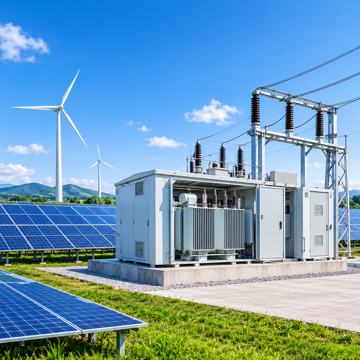
A solar microgrid lives or dies by its weakest electrical link. The step-up transformer station is rarely the most visible component, yet it determines whether the array can deliver stable power at the point of interconnection—and whether the system survives islanded operation when the grid disappears.
The collection and step-up sequence.
Inverters output AC at 480 V or 600 V. That low-voltage power must be raised to a medium-voltage collection level—typically 13.8 kV, 24.9 kV, or 34.5 kV—before it reaches the substation or PCC. Each inverter block or cluster feeds a dedicated step-up transformer, often packaged in a box-type substation. Getting this sequence right means treating the transformer as an active design element, not a passive catalog item.
Sizing and transformer choice.
A common mistake is to add up inverter nameplate ratings and order the nearest standard kVA size. Industry practice sizes the transformer at 10–20% above the sum of inverter AC ratings to absorb irradiance peaks and cloud-edge effects. For oil-immersed units, loading should stay at or below 80% to manage insulation aging under daily thermal cycling. Oil-immersed transformers remain the economical choice for larger ground-mounted blocks, with lower upfront cost and better heat dissipation than dry-type alternatives. Critically, step-up duty is not a reversed step-down application: winding energization, tap arrangement, and grounding must be verified for export conditions, not assumed. A solar microgrid transformer station therefore demands a transformer specified for cyclic overload, not continuous base loading.
Protection and grounding.
IEEE 1547 requires DER step-up transformers to maintain a grounded configuration on the EPS side, and that effective grounding persist through islanded mode. Overcurrent and earth-fault relays (50/51, 50N/51N) coordinate with inverter anti-islanding functions; the transformer must ride through faults long enough for downstream protection to clear without nuisance tripping.
Outdoor enclosure, thermal design, and ingress protection.
A box-type substation exposed to sun, dust, and temperature swings needs IP54 on HV and LV compartments as a practical baseline; oil tanks and critical seals may require IP68. Thermal design matters as much as the IP number: ONAN cooling with optimized radiators, low-level ventilation, and shading on the LV compartment keep top-oil temperature rise within limits during summer peaks. In coastal or high-dust sites, IP65 enclosures with corrosion-rated coatings are often warranted.
From datasheet to purchase order.
A reliable procurement process starts with a technical specification that locks in kVA, voltage ratio, impedance, vector group, tap range, losses, protection functions, and enclosure rating—not just a price per unit. Bid evaluation should weight technical compliance alongside commercial terms, and factory acceptance tests—routine tests, temperature-rise verification, and protection relay calibration—should be witnessed or documented before shipment. This is where a supplier with integrated oil-immersed transformer and switchgear capability, such as Zhongmeng’s S20/S22 high-efficiency oil-immersed platforms and photovoltaic box substations, shortens the gap between a parameter table and a commissioned solar microgrid transformer station. The step-up station is not a commodity; it is the controlled interface between an intermittent source and a grid that expects predictability.
Equipment layers and pre-purchase confirmation.
The step-up chain resolves into three equipment layers, and each layer has to be locked in the technical specification before a purchase order is raised.
Layer 1 - Inverter and low-voltage side
Inverters output AC at 480 V or 600 V, and each inverter block or cluster feeds a dedicated step-up transformer packaged at this level.
Layer 2 - Medium-voltage collection
Low-voltage power is raised to 13.8 kV, 24.9 kV, or 34.5 kV, usually inside a box-type substation, before it reaches the substation or the PCC.
Layer 3 - Substation and point of interconnection
This layer holds the grounded configuration on the EPS side required by IEEE 1547, the 50/51 and 50N/51N relays, and the interface where an intermittent source must look predictable to the grid.
Checklist item 1 - Nameplate and electrical parameters
kVA rating set 10–20% above the sum of inverter AC ratings, voltage ratio, impedance, and vector group.
Checklist item 2 - Tap range and loss guarantee
Tap range verified for export conditions rather than assumed from a step-down duty, with guaranteed losses stated in the specification.
Checklist item 3 - Protection functions and coordination
Overcurrent and earth-fault relays (50/51, 50N/51N) coordinated with inverter anti-islanding, with fault ride-through long enough for downstream clearing.
Checklist item 4 - Enclosure, cooling and test evidence
IP54 on HV and LV compartments as baseline, IP68 for oil tanks and critical seals, IP65 in coastal or high-dust sites, ONAN cooling, plus witnessed routine tests, temperature-rise verification and relay calibration.
Application scenarios and equipment mapping.
Scenario |
Distribution-side requirement |
Recommended equipment configuration |
Solar PV ground-mounted plant |
480/600 V inverter output raised to 13.8, 24.9 or 34.5 kV collection; irradiance peaks and cloud-edge effects; grounded EPS side that persists through islanded mode. |
Oil-immersed step-up unit on the S20/S22 platform in a photovoltaic box-type substation, sized 10–20% above the summed inverter AC rating and loaded at or below 80%, ONAN cooling with optimised radiators and LV-compartment shading, IP54 HV and LV compartments. |
Wind farm collection |
Cluster-level export to the collection voltage with cyclic load swing instead of steady irradiance; fault ride-through without nuisance tripping. |
One step-up transformer per array section, specified for cyclic overload, 50/51 and 50N/51N coordination, outdoor enclosure at IP54 baseline. |
Battery storage system |
Same interface carries export and import, so effective grounding on the EPS side has to hold through islanded operation. |
Step-up unit sized on the converter AC rating, grounded-wye configuration on the EPS side, relay settings coordinated with anti-islanding functions. |
Telecom / remote base station |
Small block fed from a medium-voltage line, unattended, and expected to survive the disappearance of the grid. |
Compact box-type substation with self-cooled ONAN unit, low-level ventilation, overcurrent and earth-fault protection, IP54 as the practical baseline. |
Mining and heavy industrial site |
Dust, sun and temperature swings on the enclosure; islanded running when the grid disappears. |
IP65 enclosure with corrosion-rated coatings and IP68 oil tank and critical seals, cyclic-overload transformer, factory acceptance tests witnessed or documented before shipment. |
Note: requirements and configurations above are read off the technical points in this article; vendor model references follow the S20/S22 oil-immersed platforms named in the text.
Frequently asked questions.
Why size the transformer above the sum of inverter ratings?
Adding up nameplate ratings and ordering the nearest standard kVA is the common mistake. Industry practice sizes the transformer 10–20% above the sum of inverter AC ratings to absorb irradiance peaks and cloud-edge effects.
Why cap oil-immersed transformer loading at 80%?
To manage insulation aging under daily thermal cycling. The step-up duty is cyclic overload, not continuous base loading, so loading should stay at or below 80% on oil-immersed units.
Can a step-down transformer simply be reversed for step-up duty?
No. Winding energization, tap arrangement and grounding must be verified for export conditions rather than assumed from a reversed step-down application.
What grounding and protection does IEEE 1547 require?
A grounded configuration on the EPS side that persists through islanded mode. Overcurrent and earth-fault relays (50/51, 50N/51N) coordinate with inverter anti-islanding, and the transformer must ride through faults long enough for downstream protection to clear without nuisance tripping.
Which ingress and cooling ratings should an outdoor box substation specify?
IP54 on the HV and LV compartments as a practical baseline, with IP68 for oil tanks and critical seals. ONAN cooling with optimised radiators, low-level ventilation and shading on the LV compartment keeps top-oil temperature rise within limits during summer peaks; coastal or high-dust sites often warrant IP65 enclosures with corrosion-rated coatings.
Table of Contents
- The collection and step-up sequence.
- Sizing and transformer choice.
- Protection and grounding.
- Outdoor enclosure, thermal design, and ingress protection.
- From datasheet to purchase order.
-
Equipment layers and pre-purchase confirmation.
- Layer 1 - Inverter and low-voltage side
- Layer 2 - Medium-voltage collection
- Layer 3 - Substation and point of interconnection
- Checklist item 1 - Nameplate and electrical parameters
- Checklist item 2 - Tap range and loss guarantee
- Checklist item 3 - Protection functions and coordination
- Checklist item 4 - Enclosure, cooling and test evidence
- Application scenarios and equipment mapping.
- Frequently asked questions.