EN

A microgrid combines distributed energy resources (DERs) such as solar, storage, and generators with loads, and it must operate both grid-connected and islanded. Microgrid switchgear sits at the center of this system. It does not simply carry current; it decides where power flows, what gets isolated, and how the microgrid stays safe when conditions change.
1. MV and LV Architecture
A typical microgrid organizes power distribution across two voltage layers, each with its own switchgear and protection scheme.
Medium-Voltage Side
The MV side collects power from distributed energy resources and connects to the utility grid. MV switchgear typically includes a main incoming breaker, a disconnect switch, and feeder panels for each generation source. This layer handles higher fault currents and requires robust arc-flash protection.
Low-Voltage Side
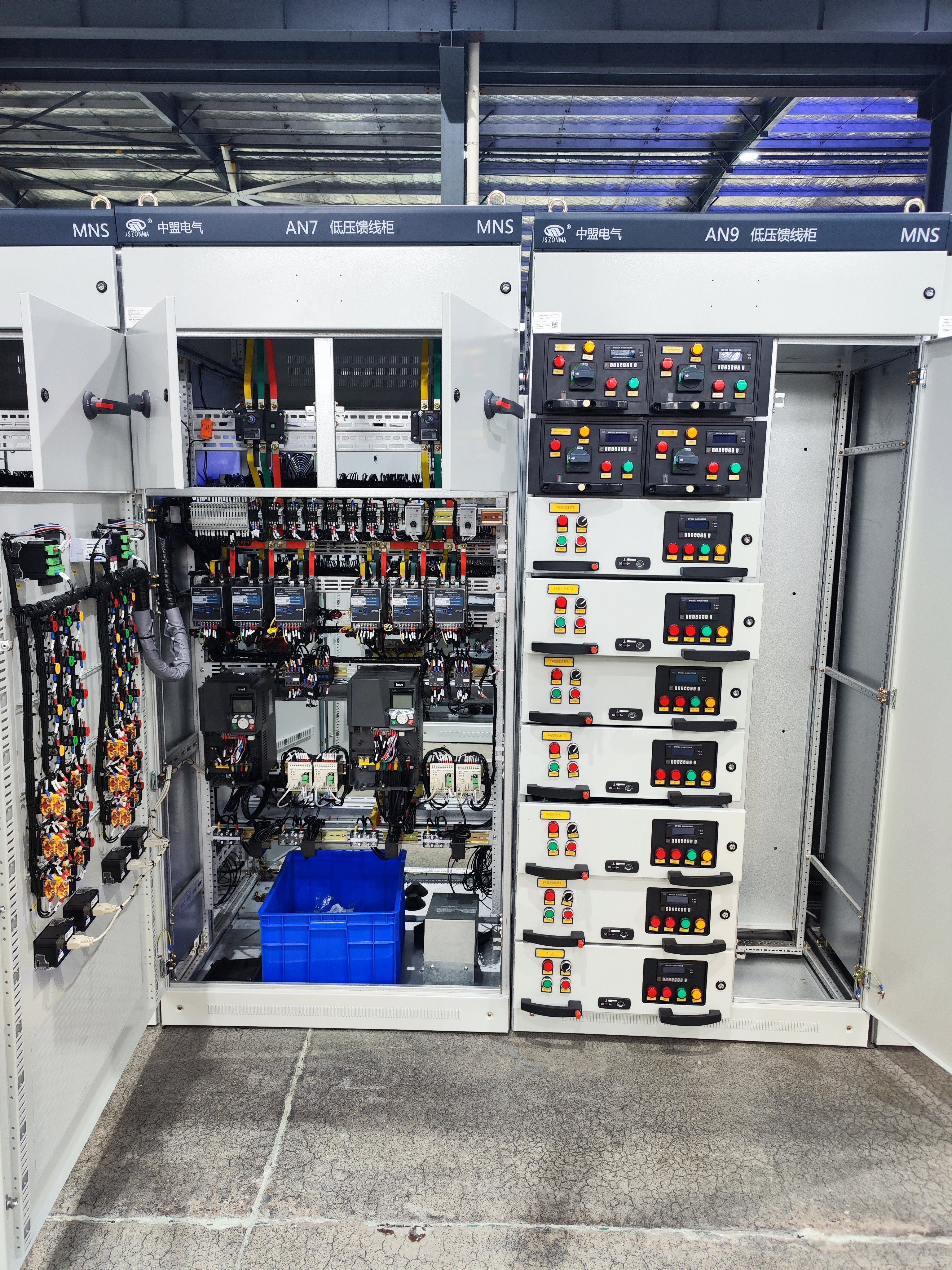
The LV side distributes power from the secondary side of transformers to end-user circuits and smaller loads. LV switchgear serves branch circuits with molded-case breakers and smaller bus arrangements. The separation between MV and LV keeps fault levels manageable and allows each layer to be protected independently.
2. Breakers, Disconnects, and Busbars
Three core devices form the backbone of any switchgear assembly, each serving a distinct and indispensable role.
Circuit Breakers
Circuit breakers detect and interrupt fault currents automatically. They protect downstream equipment and prevent faults from cascading through the system. In MV applications, vacuum or SF6 breakers are common; in LV, molded-case designs prevail.
Disconnects and Busbars
Disconnects provide a visible air gap for safe maintenance, ensuring circuits are de-energized before work begins. Busbars tie everything together, providing a common electrical node for multiple sources and loads. In MV switchgear, an air switch or draw-out breaker serves as the primary disconnect; in LV switchgear, a molded-case breaker often fills this role.
Each device has a clear job, and none can be skipped without weakening the overall safety of the installation.
3. Fault Isolation and Graded Protection
When a fault occurs, the protection system must isolate the minimum affected zone while keeping the rest of the microgrid running.
Coordination and Selectivity
The breaker closest to the fault should trip first. Backup relays behind it wait briefly and trip only if the primary protection fails. This principle, known as coordination or selectivity, ensures that a single fault does not cascade into a wider outage.
Dual-Mode Challenge
In a microgrid, the challenge grows because fault current in islanded mode can be much lower than in grid-connected mode. Protection settings must work reliably in both states. Modern digital relays with adaptive settings can switch between protection profiles based on the operating mode, ensuring consistent selectivity regardless of whether the microgrid is connected to the utility or running independently.
4. Grid-Connected and Islanded Transitions
The point where the microgrid meets the utility grid is the most critical node in the entire system.
Interconnection Switchgear
An interconnection switchgear sits at the point of common coupling. When the utility grid experiences a fault, this switchgear must isolate the microgrid quickly while keeping local loads powered. During a planned islanding event, it opens at the precise moment and signals DER controllers to adjust their output.
Fast Switching and Communication
Fast-acting breakers combined with communication-based logic help avoid unnecessary outages and protect both sides of the transition. When islanding occurs, DER inverters must shift from current-source to voltage-source behavior to maintain stable frequency and voltage. The switchgear and its associated controllers coordinate this handover.
5. Interfaces with Transformers, Inverters, and Controls
Switchgear does not operate in isolation. It is deeply integrated with the broader microgrid ecosystem.
Transformer and Inverter Connections
Switchgear connects to step-up and step-down transformers that bridge MV and LV levels, and to the output circuits of inverters that convert DC from solar panels or batteries into AC. Proper coordination between switchgear ratings and transformer/inverter capacities is essential for reliable operation.
Communication Protocols
Modern breakers and protection relays exchange data over protocols such as Modbus or IEC 61850, allowing the microgrid controller to monitor switch status and issue commands remotely. Without these communication links, coordinated islanding and black-start restoration become impossible.
6. Selection Essentials
Choosing the right switchgear requires careful attention to three critical ratings.
Rated Voltage
The rated voltage must match the system level. For MV applications, common ratings include 11 kV, 22 kV, or 33 kV. For LV, the standard is typically 380/220 V. Selecting the correct voltage class ensures insulation integrity and long-term reliability.
Short-Circuit Withstand
The short-circuit withstand rating must exceed the maximum fault current available at the installation point. In grid-connected mode, utility contribution can drive fault currents very high; in islanded mode, inverter-based sources contribute less but still require adequate withstand capacity.
Enclosure Protection
Enclosure protection depends on the installation environment. Indoor switchgear in clean rooms typically requires IP30, while outdoor or harsh-environment installations need IP54 or higher. Internal arc rating and insulation type also deserve attention for personnel safety and equipment footprint.
Additional considerations for microgrid applications include ambient temperature, humidity, salt spray exposure, and the specific derating curves required at elevated altitudes. Environmental factors directly influence both material selection and maintenance intervals.
7. Application Scenarios
Application Scenario |
Key Equipment |
Key Requirements |
Solar PV Plant |
MV collector switchgear, LV inverter AC combiner boxes |
DC disconnects, anti-islanding, grid-code compliance |
Wind Farm |
MV ring main units, LV turbine control panels |
Variable output handling, frequent switching capability |
Energy Storage System |
MV/LV transfer switchgear, battery DC disconnects |
Bidirectional power flow, fast fault clearing for Li-ion |
Telecom Base Station |
LV dual-source ATS, DC power distribution board |
Seamless transition, remote monitoring via SNMP/Modbus |
Mining Operation |
MV mobile substations, LV underground distribution |
High fault levels, rugged enclosure, explosion-proof |
8. Frequently Asked Questions
Q1: What is microgrid switchgear and why is it important?
Microgrid switchgear is the centralized distribution and protection equipment that manages power flow between distributed energy resources, loads, and the utility grid. It ensures safe operation in both grid-connected and islanded modes, provides fault isolation, and enables seamless transitions between operating states.
Q2: What is the difference between MV and LV switchgear in a microgrid?
MV switchgear operates at medium voltage levels (typically 11 kV to 33 kV) and handles power collection from DERs and utility interconnection. LV switchgear operates at lower voltages (380/220 V) and distributes power to end loads. The two layers are separated by transformers and protected independently.
Q3: How does protection coordination work in a microgrid?
Protection coordination follows the principle of selectivity: the breaker closest to the fault trips first, with backup relays providing redundancy. In microgrids, adaptive protection settings are required because fault currents differ significantly between grid-connected and islanded modes.
Q4: What communication protocols are used in modern microgrid switchgear?
Common protocols include Modbus RTU/TCP, IEC 61850 (GOOSE and MMS), and DNP3.0. These enable real-time status monitoring, remote switching commands, and coordinated protection logic between the switchgear and the microgrid controller.
Q5: What factors should be considered when selecting switchgear for a microgrid project?
Key factors include rated voltage matching the system level, short-circuit withstand capacity exceeding available fault current, appropriate IP rating for the installation environment, internal arc classification for safety, and communication capability for integration with the microgrid controller.