EN

Microgrid transformer selection differs from ordinary distribution projects. It must handle PV, energy storage, EV chargers and other power electronic equipment, with bidirectional power flow and more harmonics. If the transformer is too small, it may overload and trip. If it is too large, it will run at light load for a long time, and no-load losses will increase electricity costs. The following six points explain the selection logic.
1. Capacity: Calculate Load First, Then Consider Expansion
Do not simply add up the nameplate power of all equipment. A common formula is:
Calculated load = Total installed power
× Simultaneity factor ÷ Power factor
The simultaneity factor is typically 0.5–0.7 for general factory buildings, 0.6–0.7 for passenger vehicle charging stations, and 0.75–0.85 for heavy-duty truck fast-charging stations. Power factor is usually taken as 0.9. After calculating the result, round up to a standard capacity and reserve 10%–20% expansion margin for later charging piles, PV modules or new loads.
Microgrid design standards also specify that transformer capacity can be selected according to the maximum continuous exchange power between the microgrid and the external grid, and that self-cooled, low-loss transformers should be preferred.
Common ratings can serve as a quick reference: 630 kVA for small distributed PV, a few chargers and limited load; 800 kVA for park-level PV-storage-charging, medium charging stations and conventional centralized PV; 1250 kVA for heavy-duty truck ultra-fast charging, large PV arrays or nodes with clear expansion plans. Long-term loading should preferably be 70%–85%. Avoid long-term full load or long periods below 50%.
2. Voltage and Frequency: Align with Grid and Source-Side Equipment
The voltage level depends on the grid connection conditions on one side and the output parameters of PV inverters, energy storage PCS and chargers on the other.
A common configuration is 10 kV high-voltage side, 0.4 kV (380 V) low-voltage side, and 50 Hz. If the energy storage PCS has a 0.69 kV output, the low-voltage side should be selected at 0.69 kV instead of forcing a standard 0.4 kV configuration. For the vector group, Dyn11 is commonly used for 10 kV/0.4 kV distribution transformers. It suppresses third harmonics well and handles unbalanced loads better, which suits microgrids with many harmonic sources.
3. Oil-Immersed or Dry-Type: Check Fire Protection Conditions First
This is first a compliance issue, then a cost and performance issue.
Dry-Type Transformers
Oil-free, flame-retardant and explosion-proof. They suit indoor, basement, densely populated or strictly fire-reviewed locations, such as commercial complexes, hospitals, data centers and underground charging stations. Their initial cost is usually 20%–30% higher than oil-immersed units of the same capacity, but for indoor projects fire compliance is a hard requirement.
Oil-Immersed Transformers
Cost-effective, dissipate heat well and have strong overload capability. They can carry 120% load for several hours without tripping. They suit outdoor independent stations, open spaces and relatively relaxed fire protection requirements, such as ground-mounted PV plants, outdoor charging stations and independent energy storage booster stations. Grade 1 energy-efficient models such as S22 have low no-load losses and an advantage in long-term operating costs.
In short: dry-type for indoor densely populated places, oil-immersed for open outdoor spaces.
4. Losses, Temperature Rise and Impedance Voltage: Look at Long-Term Cost
Microgrid transformers often run for long periods, so no-load and load losses directly affect project returns. Require products to meet GB 20052 and give priority to Grade 1 energy efficiency. For example, a 1000 kVA Grade 1 dry-type transformer can reduce no-load loss by about 30% compared with a Grade 2 unit. The extra equipment cost is usually recovered in 3–5 years through electricity savings.
Impedance voltage for conventional distribution transformers is generally 4%–6%. If multiple transformers operate in parallel, the impedance voltage difference should not exceed 10%. Temperature rise limits should comply with GB 1094.2; winding temperature rise generally should not exceed 65 K. In high-temperature or enclosed environments, heat dissipation must be specially checked.
5. Matching with PV Inverters and Energy Storage PCS
An ordinary distribution transformer has unidirectional power flow. A microgrid transformer faces three additional issues:
First, bidirectional power flow. The power direction may switch dozens or hundreds of times a day between charging and discharging. Winding mechanical strength should consider frequent forward and reverse impacts, not just ordinary unidirectional distribution standards.
Second, harmonic tolerance. PV inverters and energy storage PCS generate 3rd, 5th and 7th harmonics, causing additional winding losses and local overheating. The transformer K-factor should be no lower than K4; high-frequency switching scenarios may require K13. Short-circuit impedance should be coordinated with PCS and inverter manufacturers to avoid resonance.
Third, reserve overload margin for energy storage. Energy storage transformers are usually designed for 1-hour continuous discharge. Short-time overload capability should have margin; do not configure one-to-one based only on PCS rated power.
6. Technical Parameters to Submit Before Procurement
Before requesting quotations, provide as many of these parameters as possible:
Basic Parameters
- Rated capacity (kVA), high/low-voltage rated voltage (kV), frequency (Hz), phases, vector group (e.g., Dyn11).
Performance
- No-load loss (kW), load loss (kW), short-circuit impedance (%), temperature rise limit (K), insulation class, partial discharge.
Environment and Structure
- Indoor/outdoor installation, protection rating (outdoor enclosure not lower than IP54), cooling method, altitude, ambient temperature range.
Microgrid-Specific
- Bidirectional operation design, K-factor, harmonic spectrum or PCS parameters, short-time overload requirements, grid-connection protection coordination.
Certification
- Energy efficiency test report, type test report, GB 20052 compliance certificate.
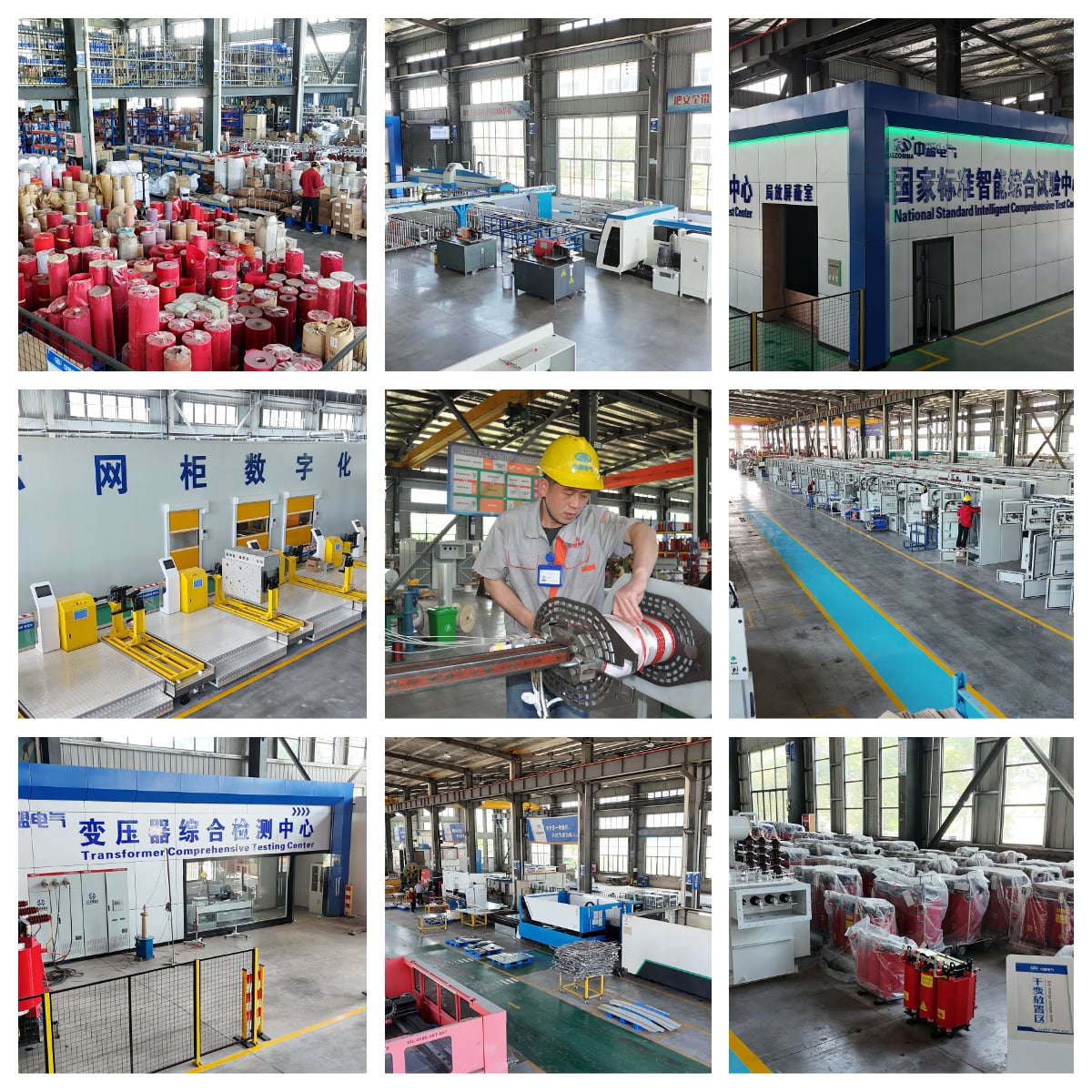
Jiangsu Unita’s Corresponding Solutions
Jiangsu Unita’s product line covers the selection needs above:
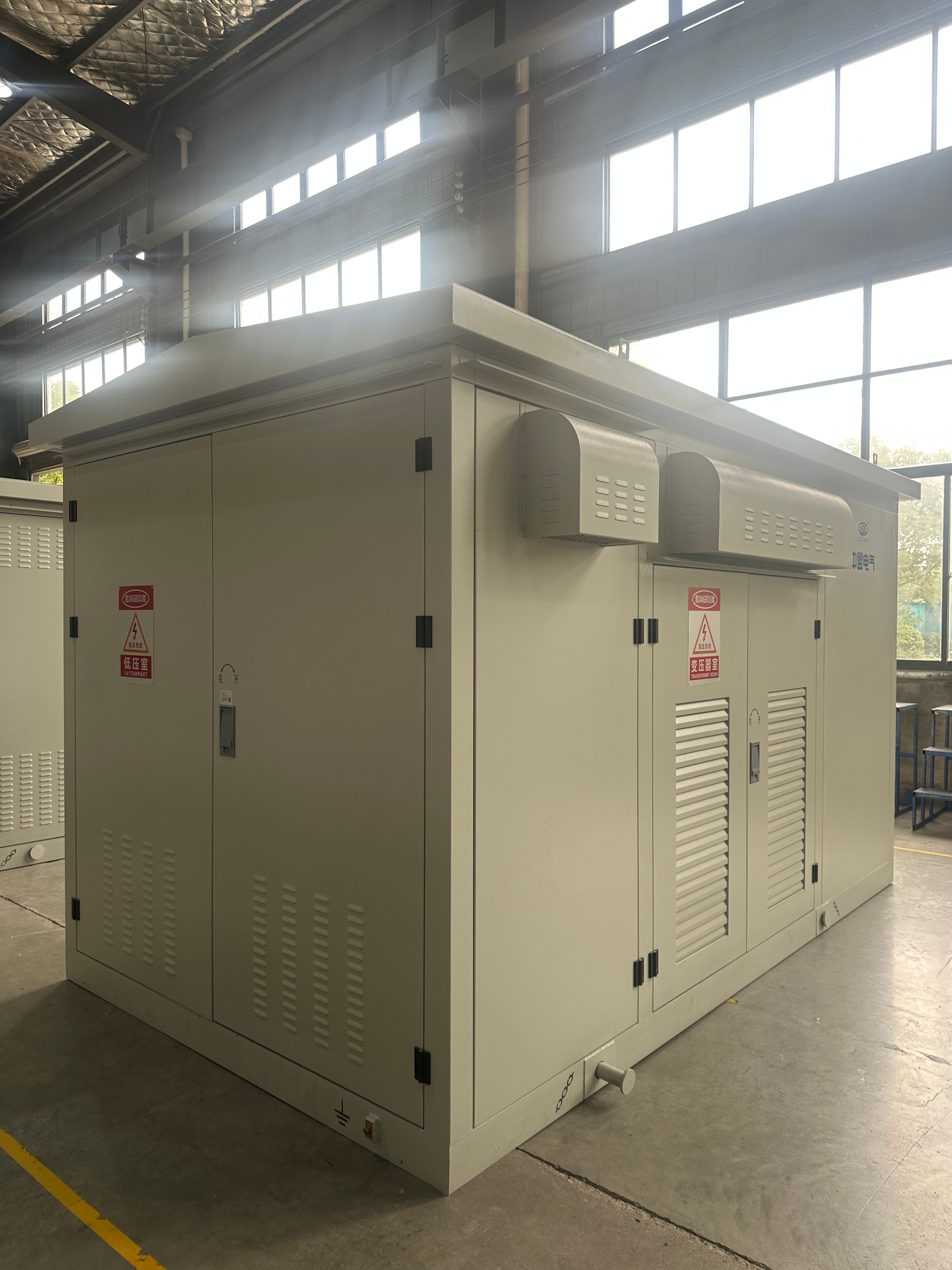
- Oil-immersed distribution transformers (S20/S22 series): For outdoor PV plants, independent energy storage booster stations and open-space charging stations. Grade 1 energy-efficient models offer low losses and strong overload capability for long-term operation.
- Dry-type transformers (SCB18 series): For indoor charging stations, commercial complexes, data centers and basements with strict fire protection requirements. Oil-free, flame-retardant, Grade 1 energy-efficient, and suitable for the harmonic environment of PV and energy storage PCS.
- Customized solutions: Targeted configurations for capacity, impedance, temperature rise, vector group and protection rating based on load curves, PCS harmonic characteristics, grid-connection conditions and expansion plans. We also support EPC contractors and owners with load verification and grid-connection documentation.