 EN
EN


News
Guide to Select the Right Three-Phase Transformer
Three-phase transformers are essential for industrial power distribution, commercial facilities, and utility grid systems. Statistics show that over 90% of global industrial and commercial power transmission depends on three-phase transformers.
Improper selection is the leading cause of on-site transformer faults. Industry data indicates 35% of transformer failures stem from incorrect parameter matching rather than quality defects. This guide simplifies three-phase transformer working principles, mainstream classifications, core parameters, and step-by-step selection methods to help engineers and buyers make cost-effective, reliable choices.
1. Working Principle of a Three-Phase Transformer
Three-phase transformers operate based on Faraday’s electromagnetic induction law, converting voltage, isolating circuits, and transmitting power through magnetic and winding mutual induction. The core structure includes a three-column silicon steel core, primary windings, and secondary windings.
When three-phase AC current flows through the primary windings, it generates balanced alternating magnetic flux in the closed core. This flux cuts the secondary windings and induces stable three-phase voltage, realizing step-up or step-down power transmission. The biggest advantage of this integrated structure is balanced three-phase magnetic circuit operation. Under normal loads, mutual offset of three-phase flux reduces no-load loss by nearly 20% compared with three separate single-phase transformers.
Winding connection modes directly affect magnetic balance. Standard configurations like Dyn11 and Yd11 ensure stable operation, while mismatched connections cause flux deviation, overheating, and increased power consumption.
2. Main Types of Three-Phase Transformers & Applications
Three-phase transformers are mainly classified by cooling method, energy efficiency, and winding connection. Each type has distinct performance data and suitable application scenarios.
2.1 Oil-Immersed vs Dry-Type Transformers (Cooling Classification)
Oil-immersed transformers dominate 85% of outdoor distribution projects. Using mineral oil for heat dissipation and insulation, they feature strong overload capacity and low cost. Their average service life reaches 25–30 years, 15% longer than dry-type models under continuous operation. They are ideal for outdoor substations, industrial parks, and rural power grids, requiring basic regular oil maintenance.
Dry-type transformers adopt epoxy resin insulation and air cooling, with no flammable components. They occupy 70% of indoor power projects such as malls, hospitals, and workshops. Though their purchase cost is 20–30% higher, their annual failure rate is only 0.3%, much lower than the 1.2% rate of oil-immersed transformers, making them the top choice for high-safety indoor environments.
2.2 Energy Efficiency Classification
Upgraded low-loss transformers have gradually replaced traditional S11 models. S13 transformers cut no-load loss by 32%, while S15 ultra-low-loss models reduce no-load loss by 40–50% and load loss by 15–20%. For a 1000kVA transformer running 24/7, the S15 version saves over 8,000 kWh annually, recouping the premium price difference within 3–5 years.
2.3 Winding Connection Groups
Dyn11: Used in 90% of modern 10kV distribution transformers. It suppresses high-order harmonics, reduces grid interference by over 60%, and withstands 25% unbalanced loads, perfect for industrial and commercial sites with variable nonlinear loads.
Yyn0: A traditional low-cost mode only suitable for fully balanced load scenarios. It tolerates a maximum of 10% load imbalance and easily causes voltage drift, mainly used in old residential power grids.
Yd11: Applied to 35kV and above high-voltage transformers, stabilizing high-voltage input and reducing peak fluctuation for mines and large regional substations.
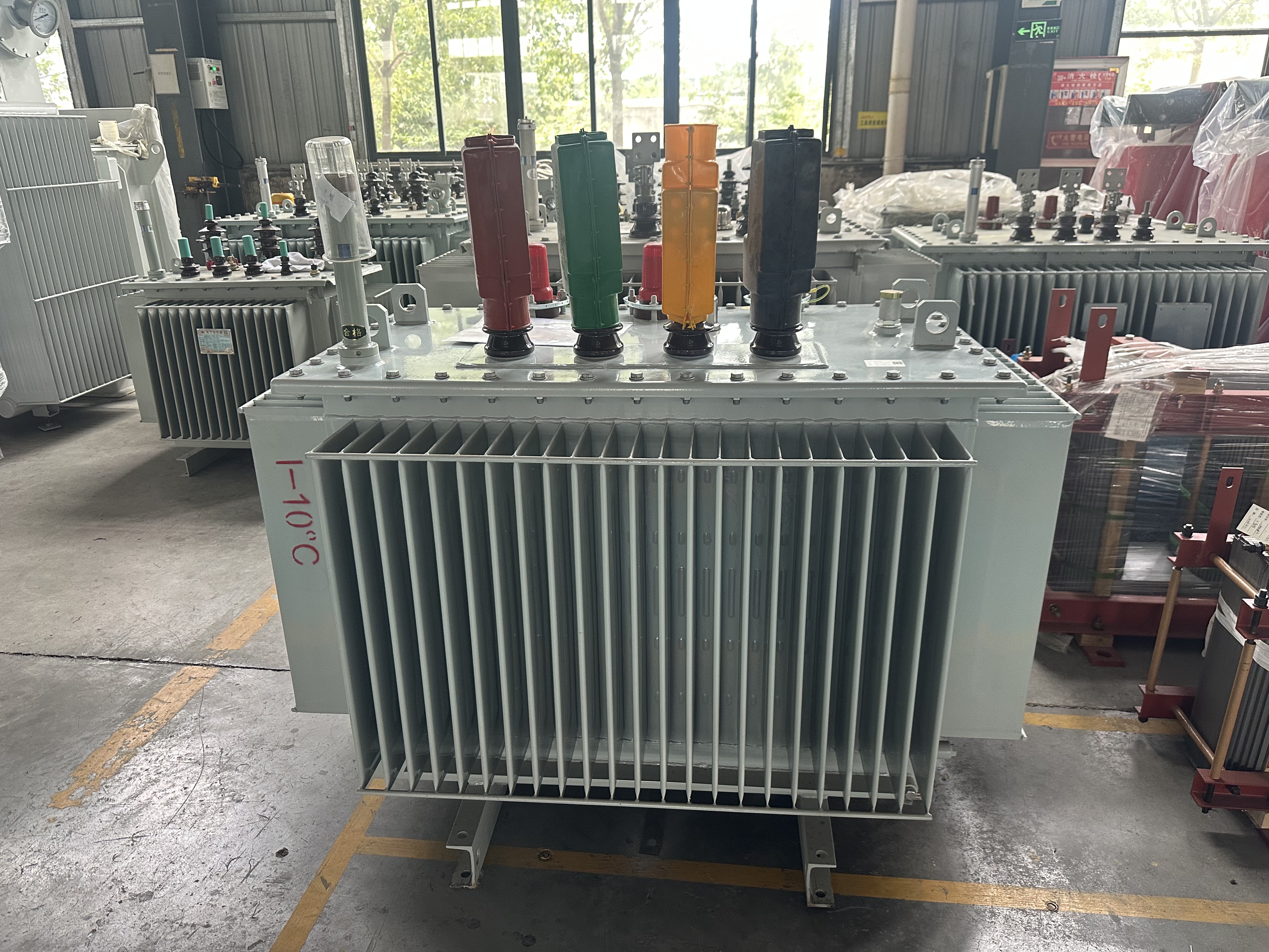
3. Core Parameters for Accurate Transformer Selection
Proper selection relies on data-based parameters rather than experience. Below are the key indicators to match project requirements precisely.
3.1 Rated Capacity (kVA)
The industry’s optimal load rate is 70%–85%. Long-term full-load operation accelerates aging, while excessive capacity raises no-load loss by over 40%. The practical selection formula: Rated capacity = total actual load power ÷ 0.75. For example, a 600kW load matches an 800kVA transformer. Units operating at 70–85% load have a 30% longer service life than full-load transformers.
3.2 Voltage Grade
The standard 10kV/0.4kV specification covers 95% of low-voltage civil and industrial scenarios. Large mines and industrial parks require 35kV/10kV or 110kV/10kV high-voltage models. Precision equipment scenarios need transformers with ±2% high-precision voltage regulation to avoid device damage from fluctuations.
3.3 Copper vs Aluminum Windings
Copper-wound transformers have 20–25% lower power loss and 15% higher overload capacity than aluminum models. Their full-load temperature rise is below 65℃, compared to 80–90℃ for aluminum windings. Copper windings suit 24-hour continuous operation; aluminum windings are cost-effective for intermittent low-load civilian projects.
3.4 Impedance Voltage
Standard 10kV transformers have 4% impedance. High-impedance models (6–8%) limit short-circuit current for factories with frequent high-power equipment startup. Low-impedance types ensure minimal voltage drop, ideal for precision electronic workshops.
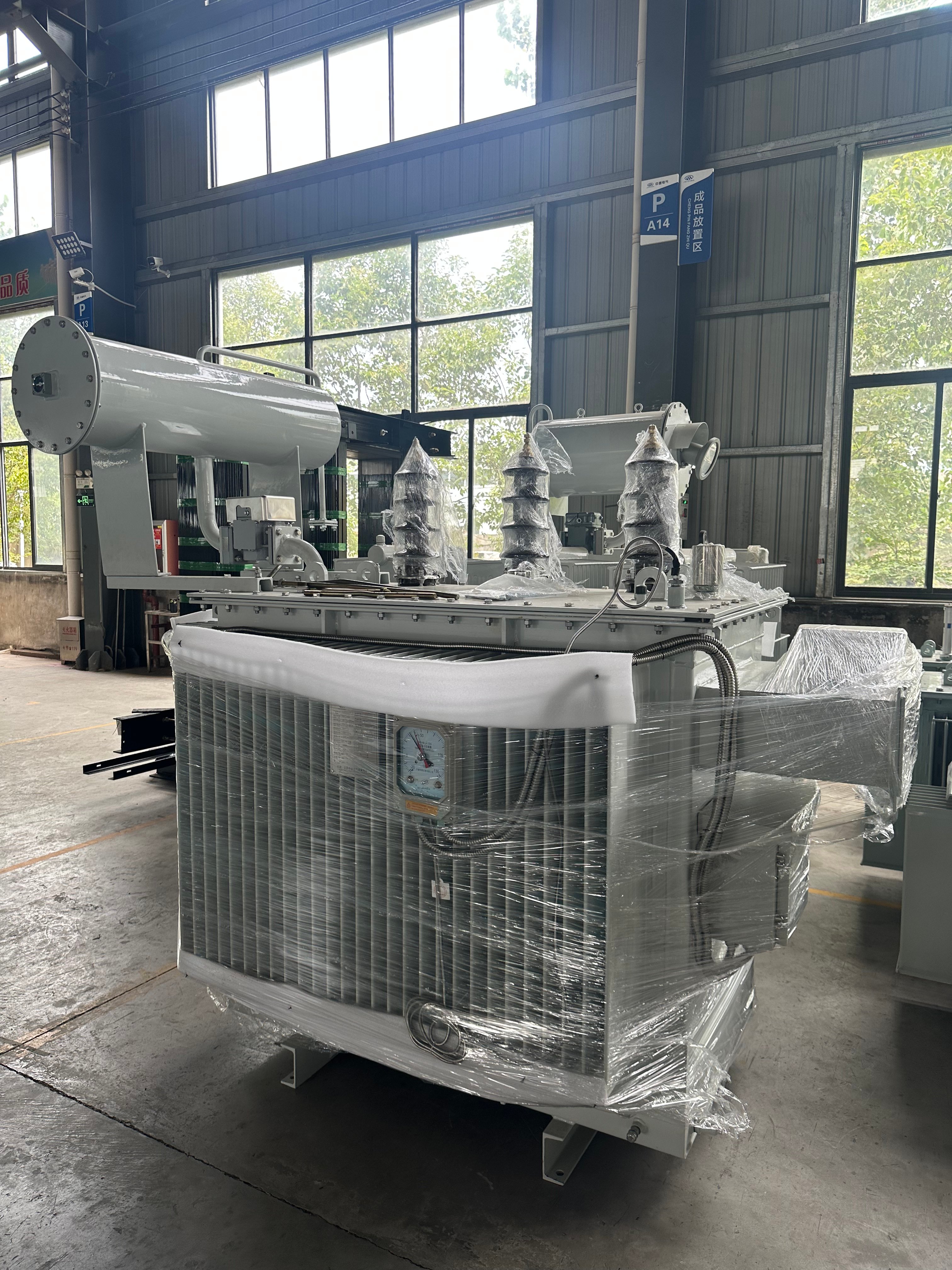
4. Step-by-Step Three-Phase Transformer Selection Process
Step 1: Match scenarios – Choose dry-type transformers for indoor high-safety sites and oil-immersed models for outdoor high-load operation.
Step 2: Confirm capacity – Calculate total load power and reserve 15–30% margin based on the 75% optimal load rate.
Step 3: Select connection group – Prioritize Dyn11 for most distribution projects to adapt to unbalanced loads and harmonic interference.
Step 4: Optimize energy efficiency and materials – Choose S13/S15 low-loss models and copper windings for long-term operation to cut daily energy costs.
Step 5: Verify safety parameters – Check impedance voltage, protection grade, and temperature rise to meet on-site environmental standards.
5. Common Selection Mistakes to Avoid
First, blind capacity expansion: Oversized transformers run under low load for long periods, increasing unnecessary no-load loss. Second, improper connection matching: Using Yyn0 for unbalanced loads causes severe voltage instability. Third, excessive cost pursuit: Low-cost aluminum and low-efficiency models increase annual power consumption by 15–20% for long-running projects.
Conclusion
Scientific three-phase transformer selection combines basic working principles, clear type classification, and accurate parameter matching. Adhering to industry optimal standards: 70–85% load rate, Dyn11 connection, S13/S15 high energy efficiency, and scenario-based structural selection, can effectively reduce failure rates, lower long-term operating costs, and extend equipment lifespan. Contact our professional team for customized transformer matching solutions for your industrial or commercial projects.
Ready to finalize your three-phase transformer specs?
JSZONMA can customize solutions for your load, supply voltage and site conditions, with full NEMA/IEEE compliance.
We also compare total ownership costs between dry-type and oil-immersed transformers and check vector group compatibility for parallel operation.
Contact us with your project needs. Our team will guide your selection and provide detailed quotes for standard or custom transformers.