 EN
EN

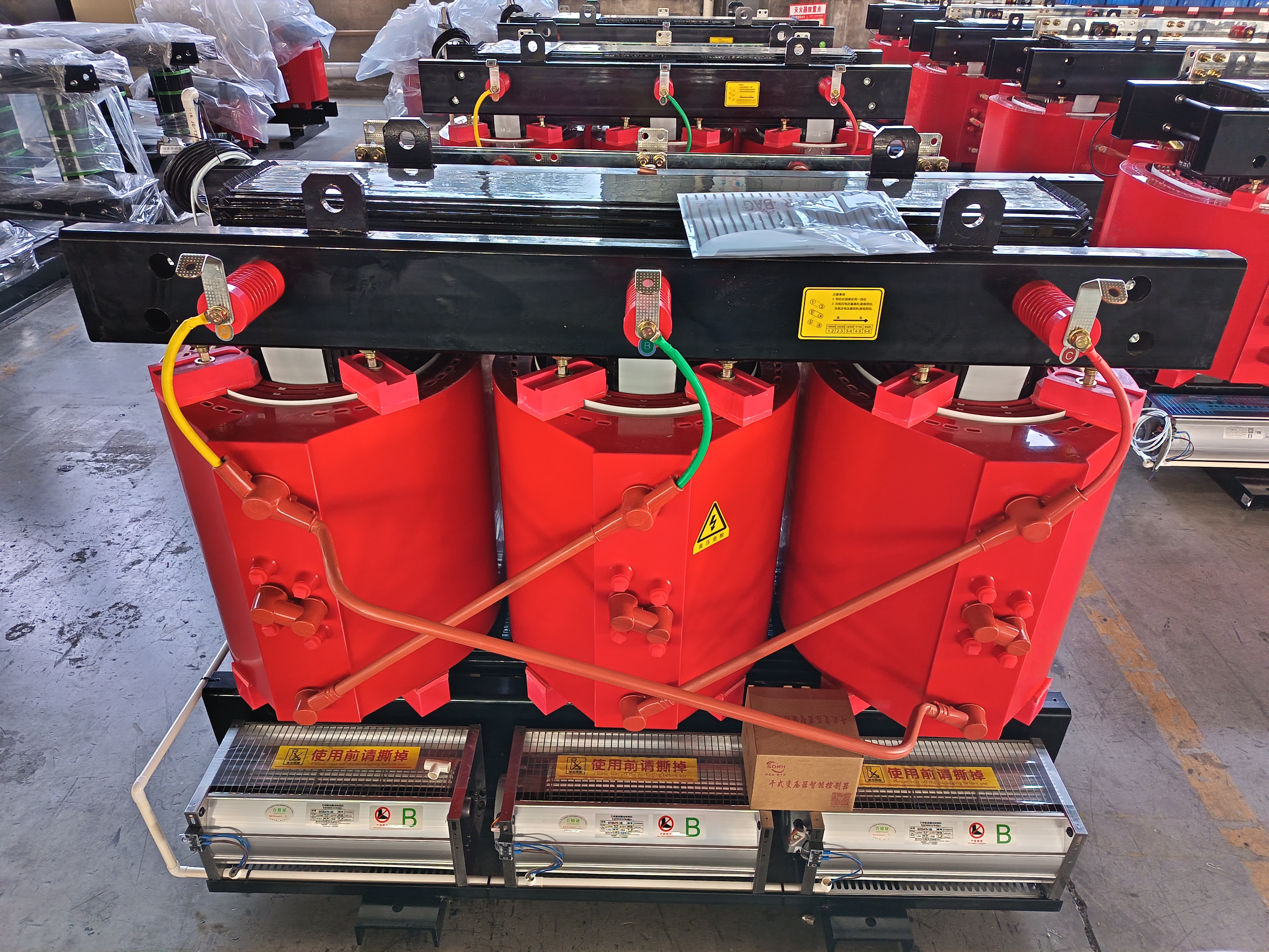
Transformers are indispensable foundational devices in modern electrical power systems, while power distribution transformer refers to a dedicated branch serving end-user power supply scenarios. These devices simplify electric energy transmission across circuits with disparate voltage levels. Engineers deploy transformers to step up voltage for bulk long-distance power transmission or step down voltage for safe industrial and residential power supply, and the rational design of all types of electric transformer units directly determines the overall efficiency, operational safety and long-term reliability of power grids. This article elaborates on power transformer design workflows, core design constraints, and mandatory technical specifications that guarantee stable operation of electrical transformer and specialized power distribution transformer products.
Understanding Electrical Transformer Design
The design of an electrical transformer is a rigorous interdisciplinary workflow covering electrical characteristics, mechanical structure and thermal dissipation performance. The core design objective is to manufacture qualified electrical transformer products that withstand preset voltage thresholds, rated power loads and harsh on-site operating environments. Detailed technical requirements vary drastically by application scenarios: power generation boosting transformers, grid transmission transformers, and on-grid power distribution transformer units bear differentiated design indicators. Every customized design scheme needs to match targeted demands including energy conversion efficiency, cooling solutions, continuous load capacity and standardized electrical safety protections.
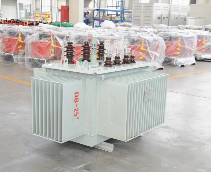
Key Factors in Designing Electrical Transformers
To deliver high-performance, fault-proof electrical transformer products, designers must prioritize the following decisive factors throughout the whole development phase:
Core Design: Magnetic core materials and geometric shapes dominate the energy conversion efficiency of any electric transformer. Manufacturers prevalently adopt silicon steel and other high-permeability magnetic materials to cut down hysteresis loss and eddy current loss, which is especially critical for high-volume power distribution transformer installed in urban power grids to reduce cumulative grid energy consumption.
Windings: Electromagnetic energy coupling and transmission rely entirely on internal winding assemblies. The turn ratio between primary and secondary coils, alongside conductive wire materials—mainly high-conductivity copper and cost-effective aluminum—jointly define the output voltage and load current of an electrical transformer. For low-voltage power distribution transformer, thickened winding wires are usually adopted to resist daily peak load impacts from residential users.
Cooling Method: Sustainable heat dissipation is the prerequisite for long-cycle operation of every electrical transformer. Based on equipment capacity, installation location and ambient climate conditions, mainstream cooling modes fall into two categories: oil-immersed cooling widely applied in large-capacity power distribution transformer, and air natural cooling adopted by small-size indoor electrical transformer.
Insulation: Layered high-strength insulation isolates windings and metal structural components to avoid internal short-circuit faults, which is the basic safety barrier of all transformer products. Industry-qualified insulating paper, transformer insulating oil and weather-resistant synthetic resins are standardized insulation materials for both industrial electrical transformer and civil power distribution transformer.
Safety and Protection Features: Since electric transformer devices operate under high-voltage working conditions, integrated protective accessories are non-negotiable. Designers need to embed insulating bushings, on-load tap changers and fault protection relays to prevent equipment burnout, a mandatory design rule for public-grid power distribution transformer to guarantee regional power supply stability.
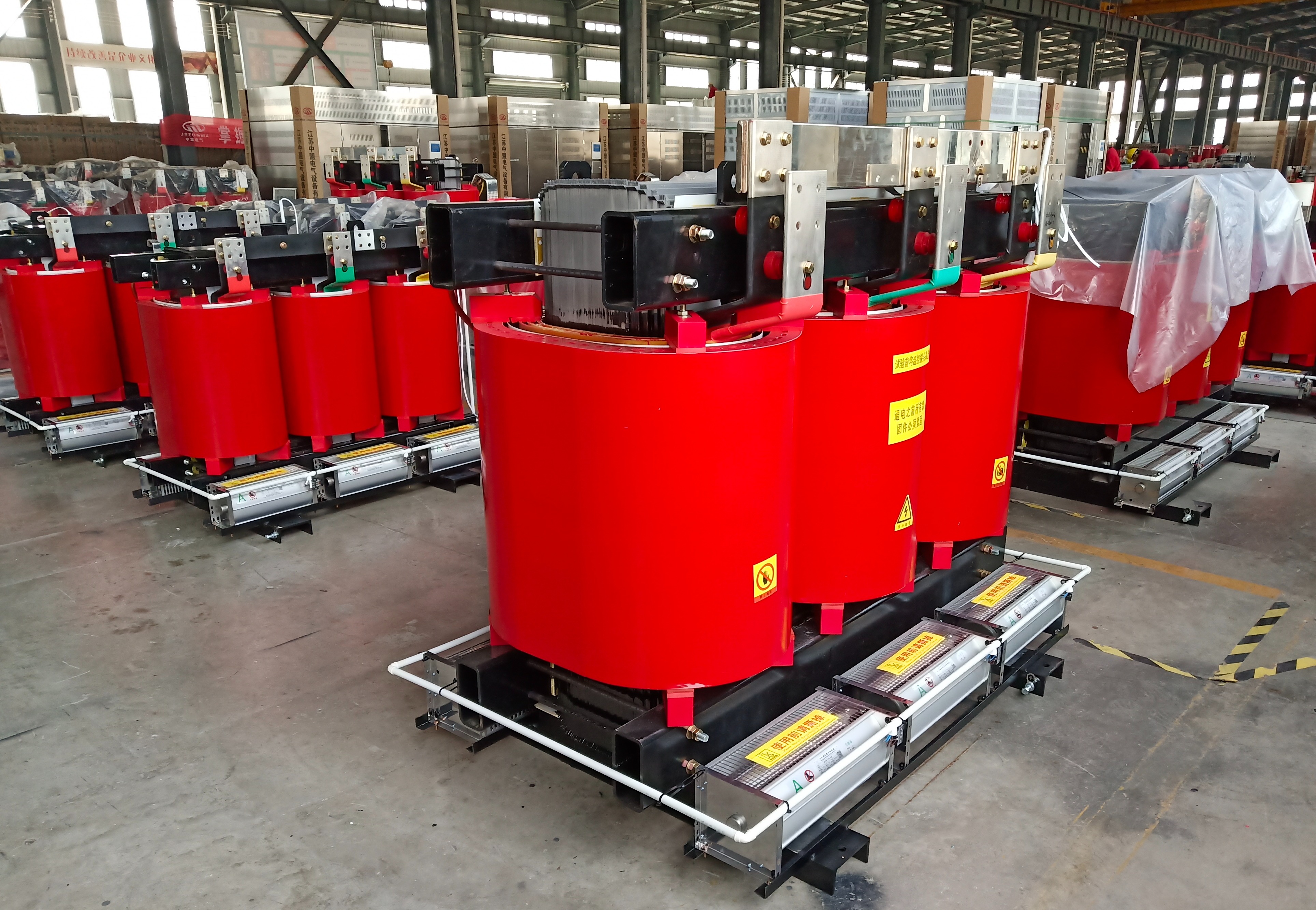
Key Transformer Specifications
Standardized transformer specifications clarify safe and efficient operation boundaries, serving as core design guidelines for developing general electrical transformer and customized power distribution transformer. The pivotal technical specifications are sorted out as follows:
Voltage Rating: This parameter refers to the maximum sustainable operating voltage, covering primary input voltage and secondary output voltage. It determines the voltage transformation range of an electrical transformer, and sets matching grid access standards for batch-installed power distribution transformer.
Power Rating: Marked in kilovolt-amperes (kVA) or megavolt-amperes (MVA), the power rating indicates the maximum bearable load capacity without overheating or structural damage. Civil power distribution transformer usually adopts medium and low power ratings to fit decentralized residential power loads.
Impedance: Transformer impedance reflects internal resistance against alternating current. It governs grid voltage drop, multi-equipment load balancing and short-circuit fault tolerance, which is a core parameter to avoid grid surge risks caused by massive electrical transformer access.
Frequency: Regional power grid frequency locks the operational frequency of all on-grid electrical transformer, commonly fixed at 50 Hz or 60 Hz. Frequency indicators directly constrain magnetic core lamination design and overall structural parameters, and cannot be modified for running power distribution transformer.
Temperature Rise: It refers to the allowable temperature increment under full-load continuous operation. Strict temperature rise limits extend the service life of electrical transformer, and prevent insulation aging failures of outdoor power distribution transformer under extreme weather.
Efficiency: Defined as the ratio of output electric power to input power, efficiency evaluates the energy-saving performance of an electric transformer. Improving operational efficiency effectively cuts grid transmission loss, and reduces long-term operation costs of urban power distribution transformer groups.
Tap Changing Mechanism: Load fluctuation triggers real-time grid voltage deviation. Built-in manual or automatic tap changers enable voltage fine-tuning, helping electrical transformer maintain output stability. This mechanism is an essential configuration for urban-grid power distribution transformer to cope with peak power consumption.
Overall, qualified electrical transformer design requires balanced iteration of electrical engineering theories, high-performance material selection and layered safety protection mechanisms. Mastering core specifications including voltage rating, impedance and cooling schemes enables engineers to develop reliable electric transformer products, as well as scenario-adaptive power distribution transformer matching power generation, transmission and distribution links. Standardized parameter configuration remains the key to maximizing efficiency, safety and stability of the whole power system.