
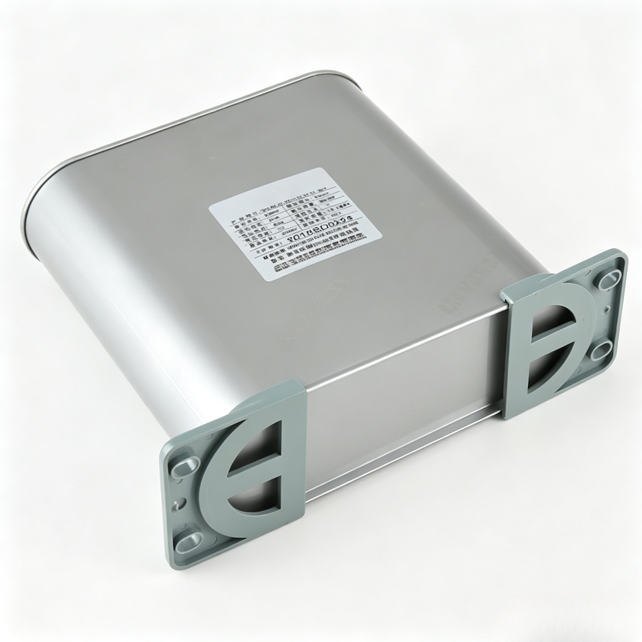
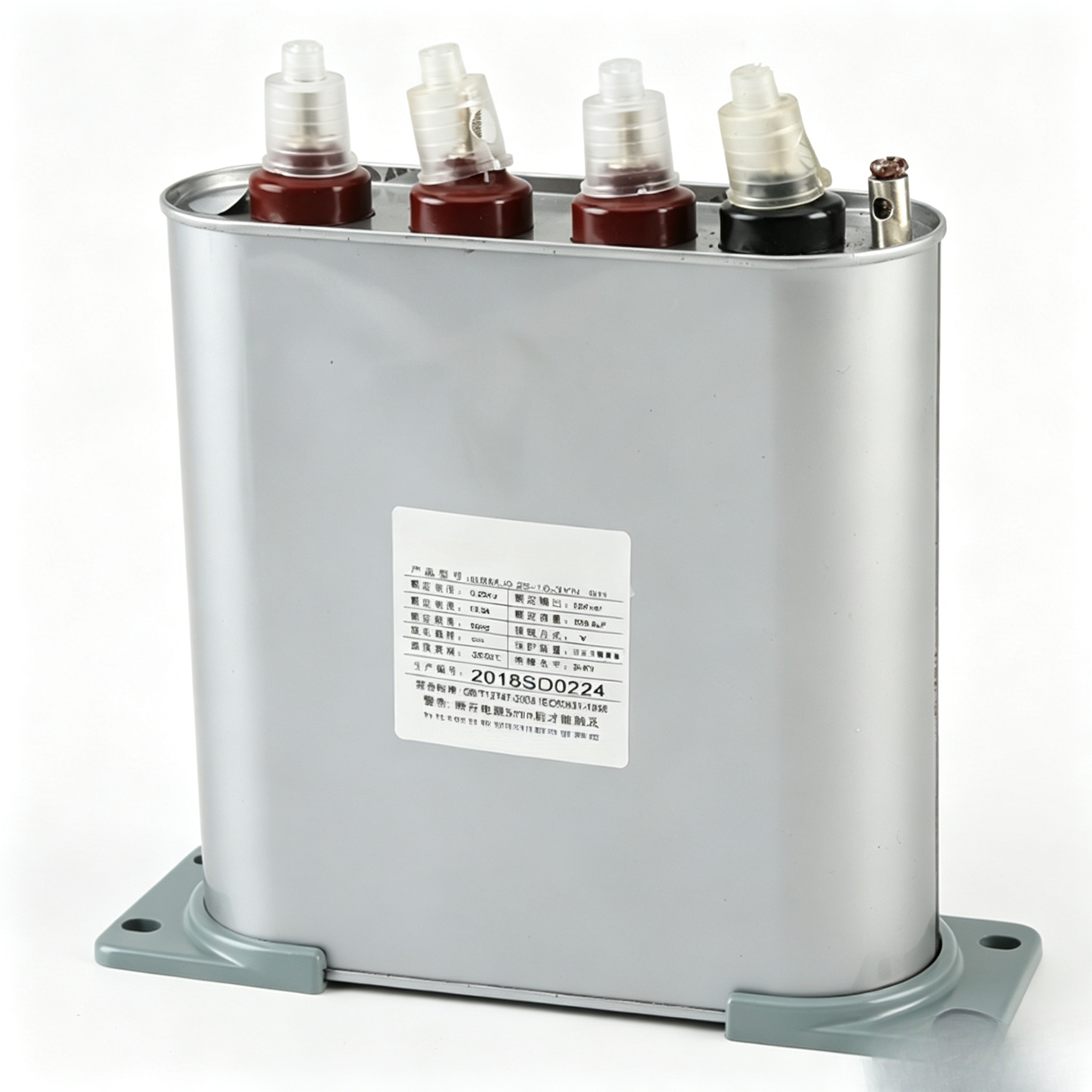
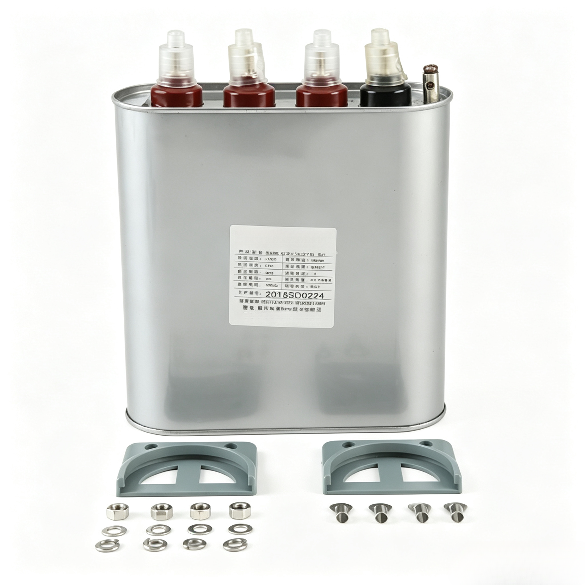
Key Features
Product Overview
BSMJ Series Self-healing Low Voltage Shunt Capacitors are applicable to AC power systems with AC 50Hz (60Hz) and rated voltage up to 1000V, for improving power factor, reducing reactive power loss and enhancing voltage quality.
Main technical parameters
Rated Voltage: 0.23~1.14kV
Rated Capacity: 1~60kvar
Rated Frequency: 50Hz or 60Hz
Capacitance Tolerance: -3~5%
Active Power Loss: ≤1.2W/kvar
Voltage Withstand Between Poles: 2.15Un for 5 seconds
Maximum Permissible Overvoltage: 1.1Un
Maximum Permissible Overcurrent: 1.3In
Self-discharge Characteristic: The residual voltage shall drop from √2Un to below 50V within 3 minutes after the capacitor is de-energized.
Compliant Standards: GB/T12747, IEC60831
Technical Parameter Table
Type BSMJ |
Rated Voltage (kV) |
Rated Capacity (kvar) |
Rated capaci tance(μF) |
Rated current (Three/Single phase)(A) |
Hight(mm) |
Drawing No. |
0.45-5-3(1) |
0.45 |
5 |
78.6 |
6.4/11.1 |
125 |
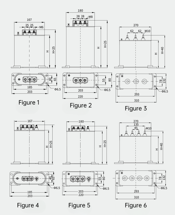
Terminal M6 as shown in Figure 1 |
0.45-8-3(1) |
0.45 |
8 |
125.7 |
10.3/17.8 |
125 |
Terminal M6 as shown in Figure 1 |
0.45-10-3(1) |
0.45 |
10 |
157 |
12.8/22.2 |
125 |
Terminal M6 as shown in Figure 1 |
0.45-12-3(1) |
0.45 |
12 |
188.6 |
15.4/26.7 |
180 |
Terminal M6 as shown in Figure 1 |
0.45-14-3(1) |
0.45 |
14 |
220 |
18/31 |
180 |
Terminal M6 as shown in Figure 1 |
0.45-15-3(1) |
0.45 |
15 |
235.8 |
19.3/33.3 |
180 |
Terminal M6 as shown in Figure 1 |
0.45-16-3(1) |
0.45 |
16 |
251 |
20.5/35.5 |
180 |
Terminal M6 as shown in Figure 1 |
0.45-20-3(1) |
0.45 |
20 |
314 |
25.7/44.4 |
220 |
Terminal M6 as shown in Figure 1 |
0.45-25-3(1) |
0.45 |
25 |
393 |
32.1/55.6 |
230 |
Terminal M6 as shown in Figure 2 |
0.45-30-3(1) |
0.45 |
30 |
471 |
38.5/66.7 |
230 |
Terminal M8 as shown in Figure 2 |
0.45-40-3(1) |
0.45 |
40 |
628 |
51.3/88.9 |
290 |
Terminal M8 as shown in Figure 2 |
0.45-50-3(1) |
0.45 |
50 |
786 |
64.1/111.1 |
330 |
Terminal M8 as shown in Figure 2 |
0.45-60-3(1) |
0.45 |
60 |
943 |
77/133.3 |
230 |
Terminal M10 as shown in Figure 3 |
0.48-5-3(1)110.5 |
0.48 |
5 |
69 |
6.0/10.4 |
125 |
Terminal M6 as shown in Figure 1 |
0.48-8-3(1) |
0.48 |
8 |
110.5 |
9.6/16.7 |
125 |
Terminal M6 as shown in Figure 1 |
0.48-10-3(1) |
0.48 |
10 |
138 |
12.0/20.8 |
125 |
Terminal M6 as shown in Figure 1 |
0.48-15-3(1) |
0.48 |
15 |
207 |
18.0/31.2 |
180 |
Terminal M6 as shown in Figure 1 |
0.48-20-3(1) |
0.48 |
20 |
276.3 |
24/41.7 |
210 |
Terminal M6 as shown in Figure 1 |
0.48-25-3(1) |
0.48 |
25 |
345.4 |
30.7/52.1 |
230 |
Terminal M6 as shown in Figure 2 |
0.48-30-3(1) |
0.48 |
30 |
414.5 |
36.1/62.5 |
255 |
Terminal M8 as shown in Figure 2 |
0.48-40-3(1) |
0.48 |
40 |
552.6 |
48.1/83.3 |
330 |
Terminal M8 as shown in Figure 2 |
0.48-50-3(1) |
0.48 |
50 |
690.7 |
60.1/104.2 |
230 |
Terminal M10 as shown in Figure 3 |
0.48-60-3(1) |
0.48 |
60 |
829 |
72.1/125 |
230 |
Terminal M10 as shown in Figure 3 |
0.525-5-3(1) |
0.525 |
5 |
58 |
5.5/10 |
125 |
Terminal M6 as shown in Figure 1 |
0.525-8-3(1) |
0.525 |
8 |
92 |
8.8/15 |
125 |
Terminal M6 as shown in Figure 1 Terminal M6 as shown in Figure 1 |
0.525-10-3(1) |
0.525 |
10 |
115 |
11.0/19 |
180 |
Terminal M6 as shown in Figure 1 |
0.525-15-3(1) |
0.525 |
15 |
173 |
16.5/29 |
180 |
Terminal M6 as shown in Figure 1 |
0.525-20-3(1) |
0.525 |
20 |
231 |
22.0/38 |
230 |
Terminal M6 as shown in Figure 2 |
0.525-25-3(1) |
0.525 |
25 |
289 |
27.5/48 |
230 |
Terminal M8 as shown in Figure 2 |
0.525-30-3(1) |
0.525 |
30 |
346 |
33.0/57 |
270 |
Terminal M8 as shown in Figure 2 |
0.525-40-3(1) |
0.525 |
40 |
462 |
44.0/76 |
270 |
Terminal M8 as shown in Figure 2 |
0.525-50-3(1) |
0.525 |
50 |
577 |
55.0/95 |
230 |
Terminal M10 as shown in Figure 3 |
0.525-60-3(1) |
0.525 |
60 |
693 |
66.0/114 |
230 |
Terminal M10 as shown in Figure 3 |
0.25-5-3YN |
0.25 |
5 |
254 |
6.7 |
125 |
Terminal M6 as shown in Figure 4 |
0.25-10-3YN |
0.25 |
10 |
509 |
13.3 |
180 |
Terminal M6 as shown in Figure 4 |
0.25-15-3YN |
0.25 |
15 |
764 |
20 |
230 |
Terminal M8 as shown in Figure 5 |
0.25-20-3YN |
0.25 |
20 |
1018 |
26.7 |
255 |
Terminal M8 as shown in Figure 5 |
0.25-25-3YN |
0.25 |
25 |
1273 |
33.3 |
290 |
Terminal M8 as shown in Figure 5 |
0.25-30-3YN |
0.25 |
30 |
1528 |
40 |
330 |
Terminal M8 as shown in Figure 5 |
0.25-40-3YN |
0.25 |
40 |
2037.18 |
53.3 |
230 |
Terminal M10 as shown in Figure 6 |
Wiring Drawing
Service Conditions
Temperature range: -25°C to 50°C
Altitude: ≤2000 m
Humidity range: ≤90% at 35°C
No harmful gases and vapors, conductive or explosive dust, and no violent vibration at the installation site.
When two or more capacitors are installed, the spacing between capacitors shall not be less than 30 mm. Effective heat dissipation measures shall be adopted in hot summer.
 EN