 EN
EN

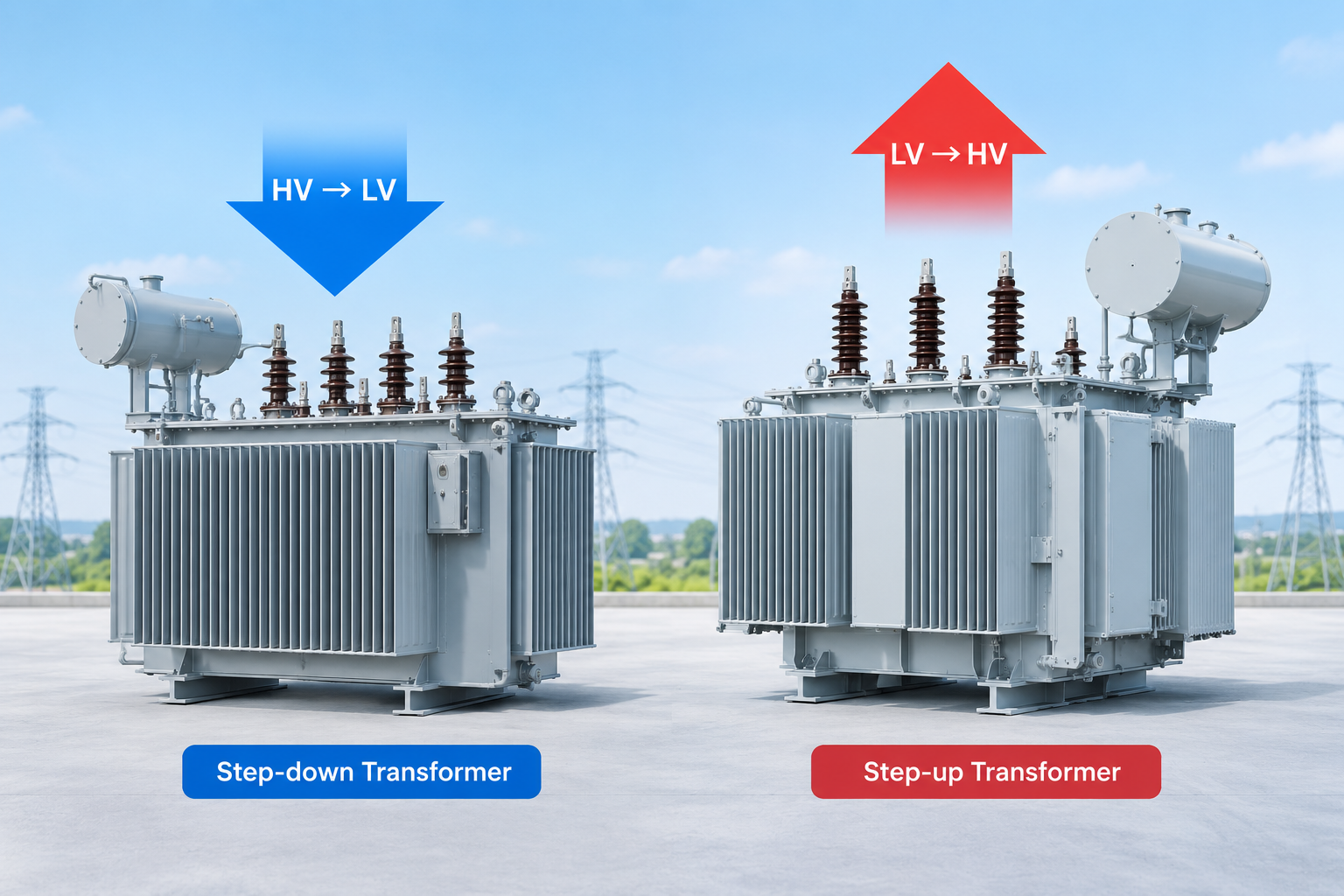
Transformers are one of the most basic and most important devices in electrical power systems. Whether it is the power output from a power plant or the safe voltage in the socket in your home, none of it is possible without the "adjusting" role of a transformer. Understanding thecore difference between step-up transformersandstep-down transformersis the key to grasping the logic of power transmission and distribution. This article will systematically explain their working principles, design differences, and application scenarios, and provide FAQ answers about common reverse-use questions.
Part1:What Is a Transformer? Basic Principles
The core function of a transformer is to transfer electrical energy between two circuits throughelectromagnetic induction. It consists of three basic parts:
- Primary winding: connected to the input power source
- Secondary winding: connected to the output load
- Magnetic core: conducts the magnetic flux
When alternating current (AC) flows through the primary winding, it creates a constantly changing magnetic field. This changing magnetic flux passes through the secondary winding and induces a voltage in it. The voltage ratio depends on theturns ratio: secondary turns ÷ primary turns.
Part2: Definition of Step-Up and Step-Down Transformers
Astep-up transformerhas more turns in the secondary winding than in the primary winding, so the output voltage is higher than the input voltage. Astep-down transformeris the opposite: the secondary winding has fewer turns than the primary, so the output voltage is lower than the input voltage.
Expressed as a formula:
Vp/Vs=Np/Ns
Here, Vs and Vp are the secondary and primary voltages, and Ns and Np are the number of secondary and primary turns. This relationship determines whether a transformer is "step-up" or "step-down."
Part3:The Core Difference: The Turns Ratio Decides Everything
Thefundamental differencebetween step-up and step-down transformers lies in the turns ratio, but this difference causes a series of connected effects:
The "see-saw" relationship between voltage and current.A step-up transformer increases voltage while reducing current proportionally. A step-down transformer does the opposite: it lowers voltage while allowing a larger current output. In an ideal case, power is conserved:VpIp=VsIs.
Differences in winding design.The secondary winding of a step-up transformer needs more turns, and in high-voltage applications it requires stronger insulation design. The primary winding of a step-down transformer has more turns, while the secondary needs thicker wire to carry the larger current.
Magnetic core design considerations.Both types of transformers use laminated silicon steel cores to guide magnetic flux, but step-up transformers usually need a larger core cross-sectional area to avoid saturation, especially in high-voltage ratio applications.
Part4:Structural and Design Differences
Beyond the turns ratio, there are more engineering-level differences in how the two are actually manufactured:
Wire specifications and insulation requirements.The secondary side of a step-up transformer withstands high voltage, so the insulation layer is thicker and the voltage withstand level is higher. The secondary side of a step-down transformer carries a large current, so the wire cross-sectional area is larger (smaller AWG number) to reduce copper loss and temperature rise.
The "trap" of voltage compensation design.Many small step-down transformers (especially those below 3 kVA) deliberately add 3%-5% extra turns in the secondary winding to compensate for voltage drop at full load. This design "works quietly" during normal use, but once the transformer is used in reverse, the compensation "works against you" and causes the output voltage to be lower than expected.
Part5: Application Scenarios
Typical applications of step-up transformers:
- At the output of power plants, to raise generator voltage to transmission level
- Grid connection of solar and wind farms, to raise low voltage to grid voltage
- Long-distance power transmission, to reduce line losses
Typical applications of step-down transformers:
- In substations, to reduce high transmission voltage to distribution voltage
- Commercial and residential power supply, to reduce voltage to a safe and usable range
- Power adapters for electronic devices
Part6: Common Misconceptions
Misconception 1: A step-up transformer "produces" electrical energy.A transformer does not produce power; it only changes the ratio of voltage to current. Output power is always less than input power (because of losses).
Misconception 2: The two can be freely interchanged.Although in principle a transformer can be used in reverse, in engineering practice there are problems such as voltage compensation and inrush current, so reverse use must be carefully evaluated.
FAQ: Common Questions About Reverse Use of Transformers
1. Can I use a step-up transformer as a step-down transformer?
Yes, but the result may not be ideal.From a physical principle point of view, a transformer is symmetrical—the turns ratio does not care which side is the "input." A step-down transformer rated 240V to 12V, if voltage is applied to the 12V side, should in theory output about 240V on the 240V side.
The problem is thatstandard transformers are optimized for a specific direction. If you use a transformer originally designed as a step-up in reverse, its voltage compensation, insulation coordination, and protection devices are all designed for the original direction. Reverse use may "work," but the output voltage may deviate from expectations, and protection devices may operate incorrectly.
Correct approach:If reverse use is truly needed, choose a transformer specifically designed for that direction or clearly rated for bidirectional operation.
2. What happens if you backfeed a step-down transformer?
Backfeeding a step-down transformer—that is, using the low-voltage side as the input—creates several practical problems:
- Increased voltage drop.Standard small transformers usually have 3%-5% turns compensation to ensure accurate full-load output voltage in the normal direction. When used in reverse, this compensation "acts in reverse," causing the output voltage to be 6%-10% lower than expected.
- Greatly increased inrush current.A transformer produces magnetizing inrush current at the moment of energization. When backfed, because the low-impedance winding (the original secondary) now acts as the primary, the inrush current can reach37 timesthe rated current or even higher (normally about 11 times in the standard direction). This can cause the upstream circuit breaker to trip frequently.
- Neutral line problem.Standard step-down transformers usually do not have a four-wire primary, so a neutral line cannot be taken from the transformer when backfeeding.
- Warranty and compliance risks.Most manufacturers clearly do not recommend backfeeding. This may void the warranty and may violate local electrical codes.
3. What is the disadvantage of a step-up transformer?
A step-up transformer is not a "better" transformer; it has its own specific limitations:
- Higher insulation cost.The secondary side of a step-up transformer withstands high voltage, so it needs thicker insulation and a larger creepage distance. This increases manufacturing cost and size.
- Thinner wire but more turns.To produce high voltage in the secondary, a large number of turns of thin wire are needed. This increases copper loss and winding resistance.
- Relatively higher no-load loss.A step-up transformer still needs to maintain core excitation at no load, and high-ratio transformers usually also have higher iron loss.
- Not suitable for all scenarios.If the goal is to obtain a large current at low voltage, a step-up transformer cannot do the job at all—what you need is a step-down transformer.Which transformer to choose depends on the application requirement, not on any judgment of "better or worse."
Conclusion
Thecore differencebetween step-up and step-down transformers lies in theturns ratio: if the secondary has more turns than the primary, it steps up; if it has fewer, it steps down. This difference then determines their different choices in current handling, insulation design, wire specifications, and application scenarios.
Both have their own roles in the power system, and neither can be missing:step-up transformers allow electricity to "travel far" efficiently, while step-down transformers allow electricity to "land safely." Understanding their differences is not only a basic part of electrical engineering knowledge, but also a necessary prerequisite for correct selection and safe use.
On the question of reverse use, the core principle is:physically possible, but engineering-wise it requires caution.Standard transformers are designed for a specific direction, and reverse use introduces practical problems such as voltage deviation, inrush current, and protection coordination. When there is a real need, priority should be given to transformers designed for bidirectional operation, or the manufacturer should be consulted for clear installation guidance.
Table of Contents
- Part1:What Is a Transformer? Basic Principles
- Part2: Definition of Step-Up and Step-Down Transformers
- Part3:The Core Difference: The Turns Ratio Decides Everything
- Part4:Structural and Design Differences
- Part5: Application Scenarios
- Part6: Common Misconceptions
- FAQ: Common Questions About Reverse Use of Transformers
- Conclusion