EN


An industrial microgrid distribution system succeeds or fails on decisions made long before the first breaker is closed: how loads are classified, how much spare capacity is reserved, how transformers and feeders are sized, and whether protection and power quality are coordinated across grid-tied and islanded modes. Reliability in a factory microgrid is not achieved by adding redundant equipment everywhere; it is achieved by designing the distribution backbone so that every critical process stays energized when the grid wavers, a transformer is taken out for maintenance, or an expansion adds a new production line. This guide walks through the distribution design choices that separate a robust industrial microgrid from an expensive collection of hardware.
Start with Load Classification, Not Equipment Selection
The first design decision in an industrial microgrid is not transformer kVA or cable size—it is deciding which loads must ride through every disturbance and which loads can be shed. Critical loads typically include process controls, safety systems, continuous-process drives, and essential cooling; general loads include non-essential conveyors, HVAC in non-sensitive areas, and office power. In microgrid reliability assessments, critical loads are classified at the highest priority tier and must be supplied to rated demand without interruption or controllability.
This classification drives the entire downstream design. A microgrid controller must be able to island a portion of the facility, verify that local generation and storage can support the critical load demand, and shed non-critical load before restoring the islanded section. Without a clear critical/non-critical split at the distribution level, the microgrid cannot execute a controlled load-shedding sequence, and the distribution system becomes a passive network rather than an active reliability asset.
Size for Load Growth, Expansion, and Spare Capacity
Industrial facilities rarely stay at their design load. Production lines are added, electric boilers and compressors replace gas-fired equipment, and EV charging appears in the yard. A practical industrial microgrid distribution system plan should therefore separate three quantities that are often conflated: present peak demand, forecasted organic growth, and contingency reserve for the loss of a source.
A common starting point for transformer sizing is a 15–25% allowance above calculated peak demand, but this is a planning anchor, not a universal rule; a 1,000 kVA transformer supplying 800 kVA has a 25% sizing margin above demand while only 20% of its rated capacity remains unused. For facilities targeting high availability, the more rigorous criterion is N-1 for medium-voltage feeders and transformer capacity—so that the failure or maintenance outage of any single transformer does not interrupt critical load. Expansion-ready design often reserves approximately 30% load headroom through spare panels and transformer margin, which reduces the cost and downtime of later retrofits.
The key is to separate equipment spare capacity from diversity and motor-start allowances, and to define the measurable triggers—sustained demand growth or a committed project—that justify the next capacity increment. Without those triggers, spare capacity either becomes stranded or is repeatedly inflated on paper without a real expansion plan.
Transformer Capacity and Low-Voltage Feeder Configuration
Transformer selection in an industrial microgrid should account for daily load swings, harmonic-rich loads, and the need for voltage control. Transformers with significant daily load variation may use on-load tap changers, and units should be selected with cooling and winding configurations that match the installation environment. In practice, the low-loss core and foil-winding construction, combined with Dyn11 vector groups and electromagnetic shielding, help attenuate characteristic harmonics before they propagate into the LV network.
On the low-voltage side, feeder configuration determines whether the facility can isolate faults without dropping entire process areas. A double-ended arrangement with two independent incomers, a split bus, and a bus-section breaker allows each half of the switchboard to be fed from either source, so that maintenance on one transformer or incomer does not de-energize the entire lineup. Equipment and process areas can then be switched between Bus-A and Bus-B through double-ended switchboards fed by separate transformers. Radial spurs are acceptable for general loads, but critical process feeders should originate from switchgear sections that retain a live alternate source under N-1 conditions.
Feeder sizing on long motor circuits is frequently governed by starting voltage dip rather than thermal ampacity; lower transformer impedance improves voltage regulation but raises available fault level, so the two must be evaluated together. This is where integrated low-voltage switchgear—such as GGD-type AC low-voltage distribution cabinets rated to 3150 A—provides a practical building block, with flexible internal mounting and space for motor feeders, capacitor steps, and future outgoing ways.
Reactive Power, Power Quality, and Protection Coordination
Industrial microgrids are harmonic-rich environments. Six-pulse variable-frequency drives can produce current THD of 40–60%, and the 5th and 7th harmonic levels alone can exceed IEEE 519-2022 individual harmonic voltage limits at the point of common coupling. Active power filters can reduce harmonic distortion by up to 95% in suitable applications, helping to maintain current THD in the 3%–5% range and supporting IEEE 519 compliance, while also providing reactive power compensation and load balancing. For facilities with fluctuating loads from press lines, welding, or large motor starts, dynamic reactive compensation through SVG or APF modules is more effective than fixed capacitor banks alone, because the compensation follows the load rather than switching in discrete steps.
Protection coordination in an inverter-dominated microgrid requires a different mindset from conventional utility protection. Inverter-based resources limit fault current contributions to roughly 1.1–1.5 per unit of rated current, and in islanded mode the available short-circuit current can be less than twice the nominal load current—making traditional magnitude-based overcurrent coordination difficult or impossible. Directional overcurrent relays with adaptive setting groups become necessary, because the fault current direction and magnitude change when the microgrid transitions between grid-tied and islanded modes. The distribution design must therefore allocate switchgear with directional relays and enough setting groups to cover multiple operating topologies, rather than assuming one fixed relay curve will work across all modes.
Design for Maintainability and Future Expansion
A distribution system that cannot be maintained safely will eventually undermine the reliability it was built to deliver. Modular switchgear with motorized breakers, load segmentation, and defined maintenance zones allows sections to be isolated without a full-site shutdown. This modularity also supports future expansion: additional feeders, storage connections, or renewable inputs can be accommodated through reserved bus sections and spare breaker compartments rather than a wholesale switchgear replacement.
The integration trend in industrial microgrids is toward factory-prefabricated, modular equipment skids that combine transformers, HV/LV switchgear, protection, and reactive compensation in a single enclosure. Pre-assembling and testing these skids in the factory shortens site commissioning and reduces the risk of workmanship defects in cable terminations and protection wiring—failure points that are often more consequential than the major assets themselves. Integrated skid solutions also make it easier to standardize protection logic and communication across multiple expansion phases, so the distribution system remains coherent as the facility grows.
How Jiangsu Unita Supports Industrial Microgrid Distribution Design
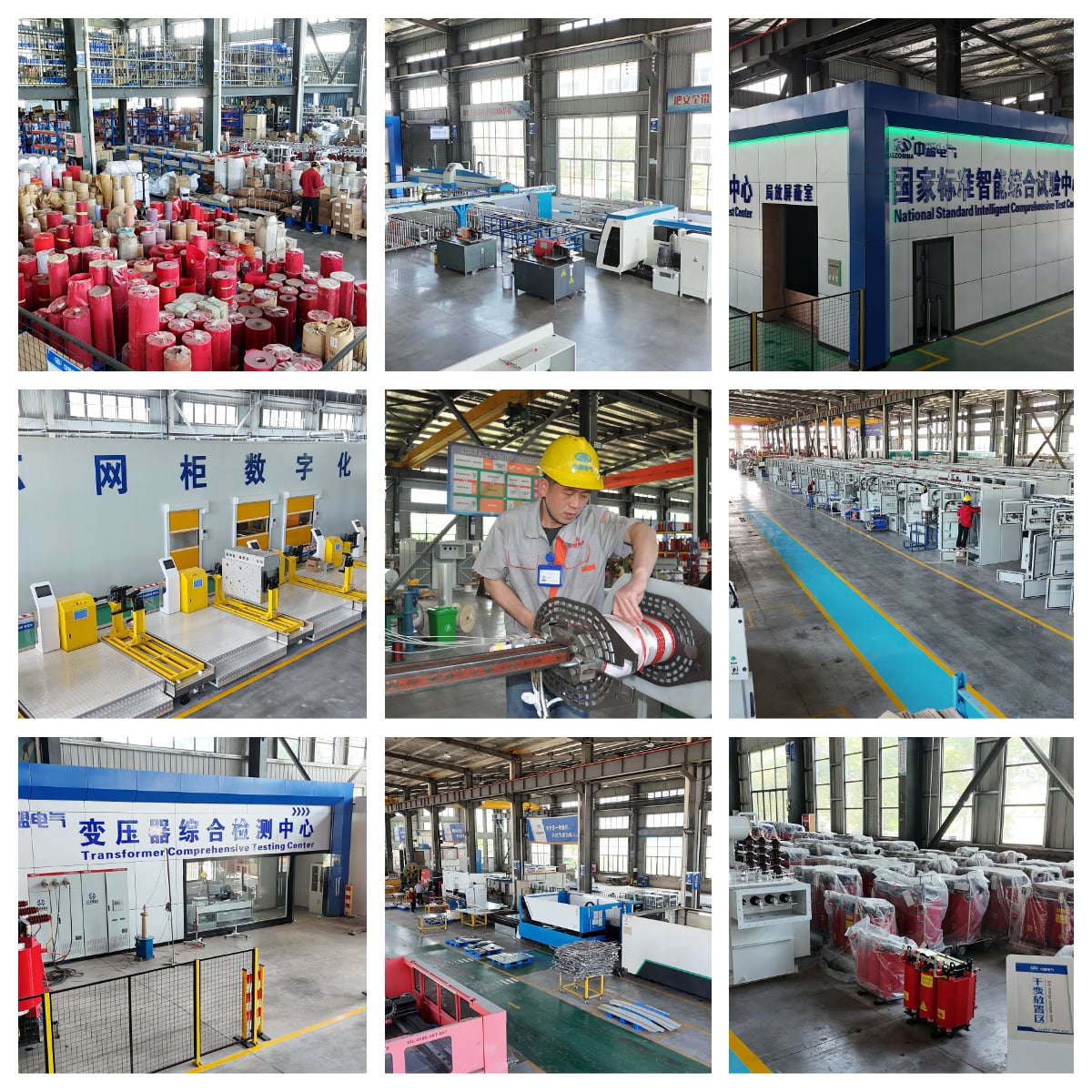
Jiangsu Unita Electric manufactures the core distribution components that sit at the center of an industrial microgrid distribution system: distribution transformers, HV/LV switchgear (including GGD-series AC low-voltage cabinets rated to 3150 A), and reactive power compensation devices including APF and SVG modules. For facilities that need integrated solutions, Jiangsu Unita’s 800V photovoltaic step-up box transformers combine transformers, HV/LV switchgear, intelligent protection, and reactive compensation in a factory-preassembled enclosure, with more than 95% of assembly and commissioning completed before shipment. The company’s converter step-up integrated cabins for commercial and industrial storage pair PCS modules, step-up transformers, SVG reactive compensation, and protection in a prefabricated skid, with dynamic reactive compensation and harmonic suppression for facilities facing large motor start impacts and load fluctuation penalties. These building blocks allow the distribution design to be assembled from coordinated, factory-tested modules rather than field-integrated components from multiple vendors.
FAQ
Q1: What is the first step in designing an industrial microgrid distribution system?
Classify loads into critical and non-critical categories before sizing any equipment. The critical/non-critical split determines what the microgrid must be able to island and supply, and it drives transformer, feeder, and protection requirements downstream.
Q2: How much spare transformer capacity should an industrial microgrid reserve?
A 15–25% margin above calculated peak demand is a common planning anchor, but N-1 transformer capacity is a more rigorous criterion for facilities with high availability targets. Expansion planning often reserves about 30% load headroom, managed against defined demand triggers rather than repeated forecast inflation.
Q3: Why is protection coordination harder in an industrial microgrid than in a conventional plant?
Inverter-based generation limits fault current to approximately 1.1–1.5 per unit, and in islanded mode the short-circuit current may be barely above load current. Magnitude-based overcurrent protection alone cannot reliably distinguish faults from normal load, so directional overcurrent relays with adaptive setting groups are required.
Q4: What power quality issues are most common in factory microgrids, and how are they addressed?
VFD-driven loads generate 5th and 7th harmonics that can exceed IEEE 519-2022 voltage limits. Active power filters and SVG-based dynamic compensation reduce harmonic distortion and correct power factor simultaneously, with APFs capable of reducing THDi by up to 95% in suitable applications.
Q5: How can the distribution system be designed for easier maintenance and future expansion?
Use modular switchgear with load segmentation and defined maintenance zones so sections can be isolated without a full shutdown. Reserve spare breaker compartments and bus sections for future feeders or DER connections, and standardize protection and communication across expansion phases to avoid redesigning the distribution backbone each time capacity is added.