 EN
EN

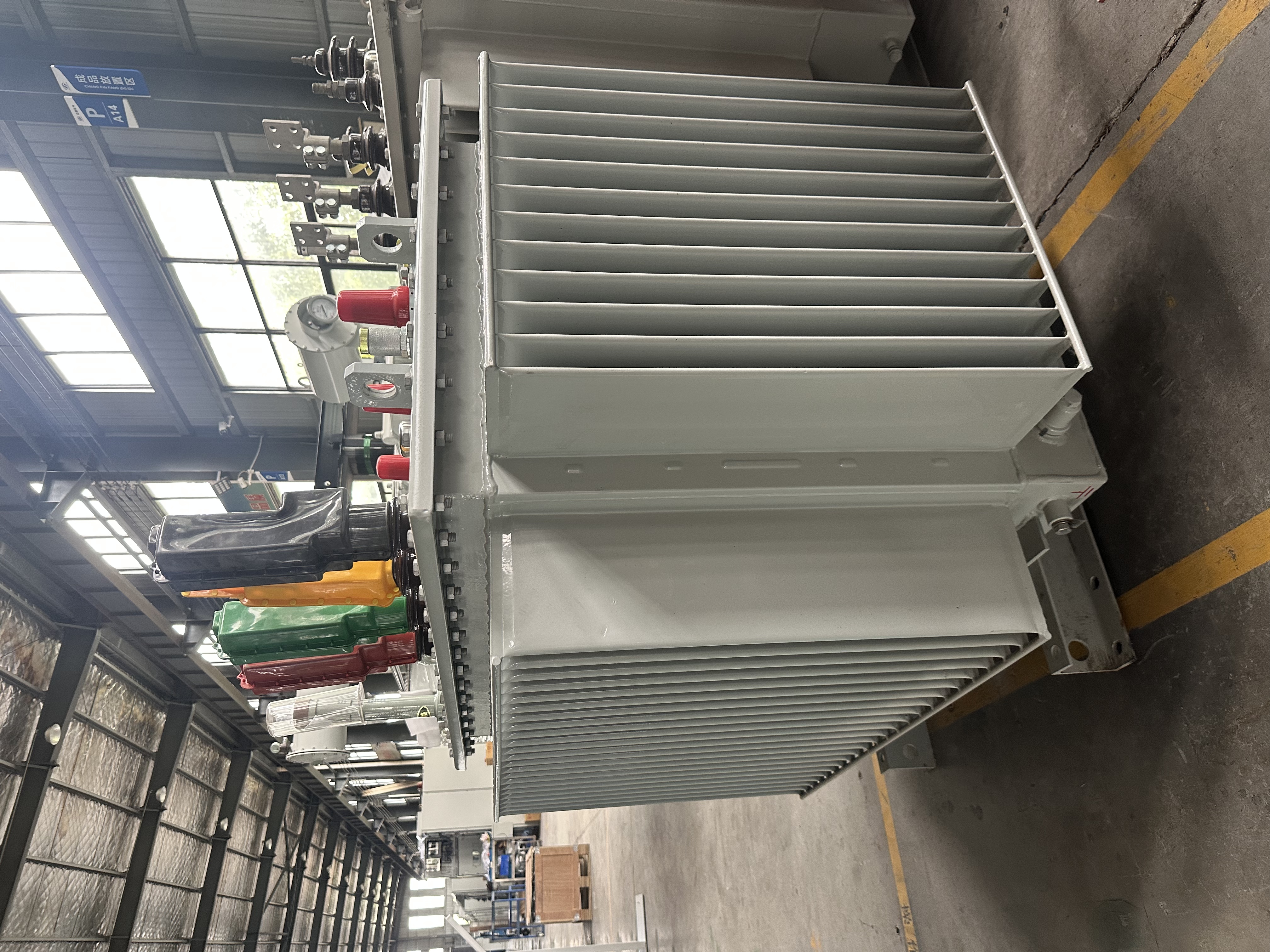
Choosing the right 10kV oil-filled transformer starts with accurate capacity calculation and a clear understanding of the 80% rule. An undersized unit overheats; an oversized one wastes capital and increases no-load losses. This guide walks through kVA sizing, oil capacity estimation, and practical selection tips for engineers and procurement teams.
What Is a 10kV Oil-Filled Transformer?
A 10kV oil-filled transformer steps down medium voltage (typically 10kV or 11kV) to a low-voltage level such as 0.4kV for end-user distribution. The core and windings are immersed in insulating oil, which provides both dielectric insulation and effective heat dissipation, ensuring stable operation and extended service life.
Oil-Filled vs. Dry-Type: A Quick Comparison
Aspect |
Oil-Filled |
Dry-Type |
Cooling |
Superior (oil circulation) |
Air/ventilation dependent |
Overload capacity |
Higher |
Lower |
Cost |
More economical |
Higher for equivalent duty |
Installation |
Outdoor, separate room |
Indoor, fire-sensitive areas |
Maintenance |
Oil testing, leak checks |
Dust cleaning, fan maintenance |
Oil-immersed transformers are preferred for outdoor installations, high-power distribution networks, and applications where cost-effectiveness and overload capability matter most.
Key Parameters You Must Know Before Selection
Rated Capacity (kVA): The maximum continuous output under rated conditions. Common 10kV ratings include 100, 250, 315, 400, 500, 630, 800, 1000, 1250, 1600, and 2000 kVA.
Voltage Ratio: Standard configuration is 10kV/0.4kV for distribution applications. Tap range is typically ±5% or ±2×2.5%.
Impedance Voltage (Uk%): Usually 4%–6% for 10kV distribution transformers. This value affects short-circuit current levels and voltage regulation.
No-Load and Load Losses: No-load loss occurs whenever the transformer is energized. Load loss increases with the square of current. Energy efficiency grades (GB 20052, IEC 60076) specify allowable limits.
Connection Group: Dyn11 is most common, providing good tolerance to unbalanced loads and suppressing third harmonics. Yyn0 is a traditional alternative with lower cost but weaker imbalance handling.
How Do I Know What kVA Transformer I Need?
Step 1: Determine Total Connected Load
List every electrical device that will draw power from the transformer. Sum their rated active power (kW). Distinguish between continuous loads (lighting, HVAC) and intermittent/impact loads (motors, welding equipment).
Step 2: Apply Demand and Diversity Factors
Not all equipment operates simultaneously. Apply a demand factor (typically 0.5–0.8 for commercial, higher for industrial) and a diversity factor to estimate the actual maximum demand.
Step 3: Convert kW to kVA
Transformer capacity is rated in kVA because heating depends on current, not power factor. Use:
kVA = kW ÷ Power Factor
For planning purposes, assume a power factor of 0.8 if actual data is unavailable.
Step 4: Apply the 80% Rule
For continuous, reliable operation, the calculated load should not exceed 80% of the transformer’s rated capacity. This provides thermal margin and accommodates load fluctuations.
Required kVA = Calculated Load (kVA) ÷ 0.8
Step 5: Add Future Expansion Margin
Transformers typically serve 20+ years. Reserve 15%–25% capacity for future load growth. Balance this against the inefficiency of chronic light-load operation.
Step 6: Select the Next Standard Size Up
Calculated values rarely match standard ratings. Choose the next higher standard kVA level.
Worked Example:
A commercial building has a calculated demand of 400 kW at 0.85 power factor.
• Apparent power: 400 ÷ 0.85 = 470.6 kVA
• Apply 80% rule: 470.6 ÷ 0.8 = 588.2 kVA
• Select standard size: 630 kVA
What Is the 80% Rule for Transformers?
Definition
The 80% rule states that a transformer’s continuous load should not exceed 80% of its nameplate kVA rating. While often treated as a firm guideline, it is fundamentally an engineering practice rooted in thermal management and reliability.
Why It Matters
Thermal Margin: Operating at 100% continuously leaves no buffer for ambient temperature extremes or temporary overloads. The 80% rule provides a safety cushion that keeps winding temperatures within design limits.
Insulation Life: Transformer insulation degrades faster at elevated temperatures. According to the 6°C rule, every 6°C increase above rated hotspot temperature doubles the aging rate. Operating at 80% load significantly reduces hotspot temperature compared to full load.
Load Growth: Real-world loads rarely remain static. The 20% headroom accommodates seasonal peaks, equipment additions, and moderate expansion without immediate replacement.
How to Apply It
The rule is straightforward:
Required kVA = Maximum Demand (kVA) ÷ 0.8
If your maximum demand is 500 kVA, select a transformer rated at least 625 kVA. The next standard size, 630 kVA, is appropriate.
When the 80% Rule Can Be Relaxed
IEC 60076-7 provides loading guidance for mineral-oil-immersed transformers, including permissible short-term overloads based on ambient temperature and load cycle characteristics. Conditions that may justify operation above 80% include:
• Load profile is stable with no extended peak periods
• Ambient temperature is consistently below the design reference
• Forced cooling (ONAF) is available
• Periodic overloads are short-duration and followed by light-load recovery
However, sustained operation above 80% accelerates insulation aging and should not be treated as a routine operating point.
Distinction from NEC 80% Rules
The 80% rule for transformer capacity planning should not be confused with NEC provisions for overcurrent protection. NEC Article 450.3 requires transformer secondary overcurrent devices sized at no less than 125% of full-load current (equivalent to an 80% utilization assumption for standard breakers). These are separate concepts: one addresses continuous loading headroom, the other addresses protection coordination.
How to Calculate Transformer Oil Capacity?
Why Oil Capacity Matters
Transformer oil serves dual functions: insulation and cooling. Oil volume directly affects heat dissipation capability, dielectric strength, and the overall thermal time constant. From a practical standpoint, oil capacity data is needed for:
• Procurement and initial filling
• Routine top-up and oil replacement planning
• Shipping weight and transport logistics
• Environmental compliance (bund sizing, spill containment)
Oil Capacity Is Not a Fixed Formula
There is no universal equation that yields exact oil volume from kVA rating alone. Oil quantity depends on:
• Core and winding dimensions
• Tank geometry
• Radiator/fin configuration
• Cooling method (ONAN vs. ONAF)
• Manufacturer design choices
The definitive source is always the manufacturer’s datasheet or nameplate.
Typical Oil Capacity Reference by Rating
The following table provides approximate values for standard distribution transformers. Actual volumes vary by design and manufacturer.
Rated Capacity (kVA) |
Approximate Oil Volume (Litres) |
100 |
30–50 |
250 |
65–100 |
500 |
125–200 |
1,000 |
200–350 |
2,500 |
500–875 |
For larger transformers, oil volume scales roughly with capacity, but the relationship is not linear due to differences in cooling surface area and tank design.
How to Estimate Oil Weight
If oil weight (rather than volume) is specified:
Oil Weight (kg) = Oil Volume (L) × Oil Density (kg/L)
Transformer oil density typically ranges from 0.86 to 0.91 kg/L at 20°C. Using 0.89 kg/L as a mid-range value:
• 200 litres ≈ 178 kg
• 500 litres ≈ 445 kg
Practical Oil Management Tips
• Use the correct oil: Always use transformer oil of the same grade and specification (e.g., mineral oil per IEC 60296) when topping up.
• Test regularly: Dielectric strength, moisture content, acidity, and dissolved gas analysis (DGA) should be performed per maintenance schedule.
• Monitor for leaks: Unexplained oil level drops indicate leakage or internal faults requiring investigation.
• Record baseline data: Document initial oil volume and weight for future reference.
Selection Tips for 10kV Oil-Filled Transformers
Match the Transformer to the Load Profile
Continuous loads (data centers, hospitals) require a different sizing approach than intermittent or impact loads (welders, large motor drives). For impact loads, consider the inrush current and voltage dip effects on other equipment.
Choose the Right Cooling Method
• ONAN (Oil Natural Air Natural): Standard for ratings up to approximately 2500 kVA. Simple, reliable, low maintenance.
• ONAF (Oil Natural Air Forced): Adds fans to radiators for higher capacity. Suitable for 3150 kVA and above. Fans can be staged to match load, saving energy at light load.
Consider Energy Efficiency and Total Cost of Ownership
A lower-priced transformer with higher losses costs more over 20+ years. Evaluate:
• No-load loss (affects cost during light-load periods)
• Load loss (affects cost at high load)
• Efficiency grade (GB 20052 Level 1 vs. Level 2)
Evaluate Installation Environment
• Indoor vs. Outdoor: Oil-filled transformers are generally preferred for outdoor use but can be installed indoors with proper fire separation, ventilation, and oil containment.
• Ambient conditions: High altitude, extreme temperatures, and corrosive environments may require design modifications.
• Fire safety: Oil-filled units require bunding, fire-rated separation, and compliance with local codes.
Verify Compliance with Standards
Confirm the transformer meets applicable standards:
• IEC 60076 series (international)
• GB 1094 / GB/T 6451 (China)
• Local utility requirements and project specifications
Request type test reports and routine test certificates before acceptance.
Common Mistakes to Avoid in Transformer Selection
• Sizing too small: Leads to overload, accelerated aging, and premature failure.
• Sizing too large: Increases no-load losses, capital cost, and inefficient light-load operation.
• Ignoring power factor: Low power factor requires higher kVA for the same kW load, effectively derating the transformer.
• Overlooking harmonics: Non-linear loads (VFDs, UPS systems) generate harmonic currents that cause additional heating. Dyn11 connection or harmonic-mitigating designs may be needed.
• Not planning for growth: Under-sizing without expansion margin leads to premature replacement.
• Treating the 80% rule as an absolute limit: It is a planning guideline, not a code requirement. Understand its thermal basis and apply engineering judgment.
• Assuming a fixed oil-to-kVA ratio: Always verify oil capacity with the manufacturer’s data.
FAQ
What is the difference between oil-filled and oil-immersed transformers?
The terms are generally interchangeable. Both refer to transformers where the core and windings are immersed in insulating oil for cooling and insulation.
How do I calculate the kVA rating for a 10kV transformer?
Convert total load to kVA (kW ÷ power factor), apply the 80% rule (divide by 0.8), add a future growth margin, then select the next standard size.
What is the 80% rule for transformers?
It is an engineering guideline stating that continuous loading should not exceed 80% of nameplate kVA, providing thermal margin and accommodating load fluctuations without accelerating insulation aging.
How do I calculate transformer oil capacity?
There is no universal formula. Oil capacity depends on manufacturer design. Use published reference tables for estimates and always verify with the transformer datasheet. Oil weight can be derived from volume using density (approximately 0.89 kg/L).
What is the typical impedance of a 10kV oil-filled transformer?
Typically 4%–6% for distribution transformers in this voltage class.
Can a 10kV oil-filled transformer be installed indoors?
Yes, but indoor installation requires fire-rated separation, adequate ventilation, oil containment (bunding), and compliance with local fire codes.
How often should transformer oil be tested?
At minimum annually, or more frequently for critical installations. Tests include dielectric strength, moisture content, acidity, and dissolved gas analysis.
Conclusion
Selecting a 10kV oil-filled transformer involves three core calculations:
1. kVA sizing: Convert load to kVA, apply the 80% rule, and select the next standard size.
2. Oil capacity: Reference manufacturer data and standard tables for planning; verify before procurement.
3. Selection factors: Match cooling, efficiency, environment, and protection to the specific application.
The 80% rule provides a practical thermal margin for reliable long-term operation, but it is a guideline, not a rigid limit. For high-value or critical installations, consult a professional electrical engineer and obtain detailed technical proposals from qualified manufacturers.
Next step: Download a transformer selection checklist or contact a manufacturer with your load profile for a tailored sizing recommendation.
Table of Contents
- What Is a 10kV Oil-Filled Transformer?
- Key Parameters You Must Know Before Selection
- How Do I Know What kVA Transformer I Need?
- What Is the 80% Rule for Transformers?
- How to Calculate Transformer Oil Capacity?
- Selection Tips for 10kV Oil-Filled Transformers
- Common Mistakes to Avoid in Transformer Selection
- Conclusion